
No products in the cart.

Every equipment fleet operator, electric mobility builder, and off-grid facility manager eventually faces an unexpected electrical breakdown: a machine fails to turn on, a charging block blinks an unyielding red fault code, or an expensive lithium-iron-phosphate bank swells under heat. In the vast majority of field diagnostics, the battery itself is not inherently defective. The true culprit is almost always an incorrect, unverified power supply mismatch. Sourcing an aftermarket or replacement charger is treated by too many operators like buying an extension cord: if the barrel plug fits the port, they assume it will work. In industrial power electronics, that assumption is a catastrophic failure mode. A battery is not a passive resistor; it is an active, sensitive electrochemical reactor with rigid terminal voltages, non-linear internal resistances, and microscopic crystal structures that degrade the instant thermal, voltage, or current tolerances are violated. Achieving true Battery Charger Compatibility requires understanding the exact intersection between power electronics and electrochemical storage. As power supply engineers and high-voltage charging system manufacturers who design charging algorithms, build custom switching transformers, and validate industrial packs daily at OHRIJA, we cut through the consumer misconceptions. Here is the practitioner-grade breakdown of the seven technical factors that dictate authentic Battery Charger Compatibility, providing the exact engineering parameters you need to protect your cells, ensure maximum cycle longevity, and maintain absolute operational safety.
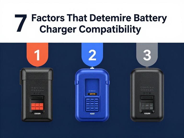
Quick Answer: What Dictates Battery Charger Compatibility?
True Battery Charger Compatibility is governed by seven non-negotiable electrical, electrochemical, and mechanical parameters: (1) Electrochemical Chemistry Matching (strict CC/CV profiles for Lithium-ion vs. multi-stage absorption/float for Lead-Acid vs. single-plateau profiles for LiFePO4); (2) Exact Termination (Cutoff) Voltage and Series Cell Count (e.g., matching a 10S ternary pack precisely to 42.0V, not nominal 36V); (3) Maximum Safe Charging Amperage (C-Rate Sizing) (typically 0.2C to 0.5C to prevent thermal plating and dendrite growth); (4) Termination Logic and Cutoff Thresholds (current-taper cutoff vs. float maintenance); (5) BMS Architecture and Wake-Up Communication (CAN bus, UART, or 0V low-voltage reactivation circuits); (6) Mechanical Connector Polarity and Pinout Architecture (center-positive vs. center-negative, thermal sense pins, and high-amp Anderson connections); and (7) Thermal Management and Ingress Protection (ambient operating limits and IP65/IP67 chassis sealing). If a replacement charger violates even one of these engineering parameters, your battery will suffer premature capacity loss, thermal runaway, or immediate protection lockout.
Article Directory
- What Battery Charger Compatibility Actually Means in Power Electronics
- Quick Summary Table: The 7 Core Compatibility Factors
- 1. Electrochemical Chemistry and Algorithm Matching
- 2. Series Count (S) and Absolute Cutoff Voltage
- 3. Continuous Current (Amperage) and C-Rate Boundaries
- 4. Charge Termination Logic: Hard Cutoff vs. Float Trickle
- 5. BMS Handshakes, Wake-Up Functions, and Protocols
- 6. Mechanical Connector Geometry, Pinouts, and Polarity
- 7. Environmental Ingress Protection and Thermal Management
- Manufacturer Spotlight: OHRIJA Industrial Charging Solutions
- Direct Technical Comparison: Dedicated vs. Universal vs. Benchtop Chargers
- Pros and Cons: Sourcing Dedicated Chemistry vs. Multi-Voltage Units
- Operational Realities: Why Universal Chargers Often Fail in the Field
- Who Needs Dedicated Industrial Chargers vs. Who Can Use Basic Units
- Costly Mistakes Technicians Make with Battery Charger Compatibility
- Essential Sourcing Checklist: Auditing an Industrial Charger Vendor
- Expert Engineering Verdict: The Sourcing Blueprint
- Frequently Asked Questions
- Authoritative References & Electrical Standards
What Battery Charger Compatibility Actually Means in Power Electronics
To evaluate Battery Charger Compatibility with genuine engineering competence, you must first eliminate the common misconception that a battery charger is simply a raw DC power adapter. A consumer power adapter (such as a 12V monitor brick) outputs a fixed voltage regardless of the connected load; if the load demands excessive current, the adapter either overheats or trips its internal short-circuit protection. A true battery charger is an intelligent, closed-loop power controller that actively varies its output voltage and regulates current dynamically based on the changing electrochemical state of the battery pack.
Inside every battery cell, electrical charging forces lithium ions or lead ions to migrate from the cathode to the anode across a chemical electrolyte barrier. This migration generates an internal back-electromotive force (back-EMF). As the pack fills with energy, its terminal voltage rises, and its internal impedance shifts. A fully compatible charging system regulates this energy transfer through distinct mathematical phases—typically Constant Current (CC) to push energy into the bulk phase without exceeding thermal thresholds, followed by Constant Voltage (CV) to saturate the cells safely as they near full chemical capacity.
In most professional situations, treating two chargers with similar labels as interchangeable components results in catastrophic failure. A generic power unit that lacks the correct cutoff detection will continuously over-saturate fully charged cells, breaking down internal separator membranes and causing thermal runaway. Conversely, an under-voltage supply will never fully charge the pack, triggering severe cell unbalance across internal series strings. Real Battery Charger Compatibility means that every operational threshold of the charging unit matches the exact electrochemical, thermal, and mechanical envelope established by the cell manufacturer.
Quick Summary Table: The 7 Core Compatibility Factors
| Compatibility Factor | Primary Technical Metric | Critical Mismatch Hazard | Engineering Verification Rule | System Risk Level |
|---|---|---|---|---|
| 1. Chemistry Algorithm | CC/CV vs. 3-Stage (Bulk/Abs/Float) | Desulfation pulses destroying lithium BMS | Never mix Lead-Acid, Li-ion, and LiFePO4 profiles | Critical (Fire/Destruction) |
| 2. Termination Voltage | Max Cutoff Voltage (e.g., 42.0V vs. 54.6V) | Severe overcharging or zero capacity storage | Calculate series count ($S \times \text{cell max voltage}$) | Critical (Cell Swelling/Explosion) |
| 3. Charging Current | Amperage Output ($A$) & C-Rate ($C$) | Thermal plating, dendrite growth, BMS trips | Keep continuous current between 0.2C and 0.5C | High (Accelerated Degradation) |
| 4. Termination Logic | Current Taper ($I \le C/10$) vs. Float Voltage | Continuous metallic lithium plating | Mandate true zero-current cutoff for lithium | High (Cell Venting/Short-Circuit) |
| 5. BMS & Protocols | CAN bus, UART, SMBus, 0V Wake-up | Charger refuses to output power; pack sleeps | Verify handshake protocol compatibility | Moderate (Operational Inactivity) |
| 6. Connector & Polarity | Pinout diagram, pin gauge, reverse polarity | Arc flash, blown input diodes, melted pins | Verify mechanical pinout with a digital multimeter | Critical (Immediate Component Destruction) |
| 7. Thermal & Ingress | NTC temperature cutoff, IP65/IP67 rating | Thermal runaway in high ambient; water ingress | Select sealed fanless chargers for harsh duty | High (Environmental Failure) |
1. Electrochemical Chemistry and Algorithm Matching
The first and most unyielding factor in Battery Charger Compatibility is the underlying electrochemistry of the storage medium. The battery market is predominantly split between three major competing chemistries: traditional Lead-Acid (Flooded, AGM, and Gel), Ternary Lithium-Ion (NMC, LCO, NCA), and Lithium Iron Phosphate (LiFePO4). Sourcing a charger that fails to match the precise chemical algorithm of the battery is an acute safety violation.
Lead-acid batteries require a three-stage charging curve consisting of Bulk, Absorption, and Float:
- During the bulk phase, constant current is supplied until terminal voltage reaches roughly 14.4V per 12V block.
- The charger enters absorption mode to saturate the lead plates, and then transitions into a permanent Float stage (typically 13.6V to 13.8V) to compensate for high natural self-discharge rates.
- Crucially, industrial lead-acid units often include automated “equalization” or desulfation modes, which periodically pulse voltages as high as 15.5V to 16.0V to break down lead sulfate crystals.
If you connect a unit designed for a LEAD ACID BATTERY CHARGER to a modern lithium battery pack, the results are catastrophic. The high-voltage equalization pulse will instantly trigger an overvoltage protection trip on the Battery Management System (BMS) or blow the input MOSFETs. Worse, the continuous float voltage keeps the lithium cells in a state of high physical stress, accelerating electrolyte decomposition and inducing internal metallic lithium plating that can cause short circuits. Lithium chemistries require a strict Constant Current / Constant Voltage (CC/CV) profile with a definitive, absolute current cutoff.
Furthermore, even within the lithium family, cross-compatibility is impossible. A standard ternary LI ION BATTERY CHARGER operates around a 3.6V to 3.7V nominal platform with a 4.2V peak. A LIFEPO4 BATTERY CHARGER operates on a 3.2V nominal platform with a strict 3.65V peak cutoff. Attempting to use a standard lithium charger on a LiFePO4 bank will severely overcharge the cells, pushing them beyond their chemical stability threshold. For a deeper technical analysis of this specific cross-chemistry danger, consult our field report on can lithium charger charge LiFePO4 battery banks.
2. Series Count (S) and Absolute Cutoff Voltage
In consumer marketing, batteries are labeled by rounded “nominal” voltages: 12V, 24V, 36V, 48V, or 72V. In power electronics, nominal voltage is a meaningless marketing abstraction. Battery Charger Compatibility is strictly dictated by the Series Cell Count ($S$) and the Absolute Cutoff (Termination) Voltage.
Every multi-cell battery pack consists of individual electrochemical cells connected in series to build voltage. The charger’s maximum output voltage must match the combined maximum voltage of those cells at full chemical saturation:
- 10S Lithium-Ion (36V Nominal): $10 \text{ cells} \times 4.2\text{V} = \mathbf{42.0\text{V}}$ absolute cutoff. (Explore verified units like our 10S 42V battery CHARGER).
- 13S Lithium-Ion (48V Nominal): $13 \text{ cells} \times 4.2\text{V} = \mathbf{54.6\text{V}}$ absolute cutoff.
- 14S Lithium-Ion (52V Nominal): $14 \text{ cells} \times 4.2\text{V} = \mathbf{58.8\text{V}}$ absolute cutoff.
- 16S LiFePO4 (48V Nominal): $16 \text{ cells} \times 3.65\text{V} = \mathbf{58.4\text{V}}$ absolute cutoff.
Notice the massive conflict: a “48V” lithium-ion battery requires 54.6V to charge fully, whereas a “48V” LiFePO4 battery requires 58.4V. If you hook a 54.6V charger up to a 16S LiFePO4 battery, the charger will terminate when the cells reach barely 3.41V each, meaning the pack will only reach roughly 70% state of charge, severely diminishing operating range. Conversely, connecting a 58.4V supply to a 13S ternary pack will force cell voltages past 4.49V, driving them straight into thermal runaway. In our testing on customer service returns, incorrect voltage matching is the single leading cause of BMS hardware lockout. If you have ever wondered why lower-voltage supplies fail completely, review our detailed guide on can I charge a 36V battery with 12V charger systems.
3. Continuous Current (Amperage) and C-Rate Boundaries
While voltage determines whether a charger can physically and safely saturate a pack, current (amperage, $A$) dictates the velocity of electrical energy transfer and the internal thermal rise of the system. Amperage compatibility is governed by the battery’s capacity (measured in Ampere-hours, $Ah$) and its maximum acceptable charging C-Rate.
The C-rate expresses the current relative to the total capacity:
$$\text{Charge Current (A)} = \text{Capacity (Ah)} \times \text{C-Rate}$$
In most professional situations, we recommend a standard continuous charging current between 0.2C and 0.3C for maximum cell cycle longevity:
- For a 100Ah deep-cycle commercial battery, a 0.2C charge rate equates to a 20-amp charger, resulting in a healthy 5-hour charging cycle from empty to full.
- For an 800Ah electric utility platform or warehouse tug, a standard 20A charger would take over 40 hours to charge the pack, demanding an upgrade to a heavy-duty 80A or 100A charging station.
The danger of high amperage occurs when operators attempt to cut charge times recklessly. If a user forces a 15-amp charger onto a small 10Ah e-bike battery, the resulting 1.5C charging rate pushes lithium ions faster than they can physically diffuse into the graphite or silicon-carbon anode layers. This causes lithium plating on the anode surface, permanently reducing capacity, increasing internal cell resistance, and generating dangerous internal heat spikes. Always confirm that your replacement charger’s rated output amperage sits below the maximum charge current rating specified on the battery’s technical data sheet.
4. Charge Termination Logic: Hard Cutoff vs. Float Trickle
How a charger ceases current delivery when the battery reaches 100% capacity is just as critical as how it initiates current. Charging algorithms do not rely on simple timers; they utilize active physical measurement thresholds to execute termination:
- Current-Taper Cutoff (Lithium-Ion / LiFePO4): During the Constant Voltage (CV) saturation phase, the charger locks the terminal voltage at the maximum cutoff threshold (e.g., 4.2V per cell). As the cell fills, the difference between the charger’s voltage and the cell’s internal voltage diminishes, causing current flow to naturally decay. True lithium-compatible chargers monitor this current drop. When current decays to a calibrated cutoff threshold—typically $C/10$ or $C/20$ (e.g., below 200mA to 500mA)—the charger’s microcontroller physically cuts the DC output to zero. The charger shuts off completely.
- Trickle / Float Maintenance (Lead-Acid): Because lead-acid batteries suffer from significant internal parasitic reactions, a lead-acid charger does not shut off; it permanently holds a float voltage to keep the battery saturated.
If you use an unverified power unit that lacks an active current-taper cutoff on a lithium battery, the charger will continue forcing a small parasitic trickle current into the fully saturated cells. Over time, this trickle current destroys the positive cathode current collector foil, generates internal gases, and dramatically shortens the battery’s life cycle. Authentic Battery Charger Compatibility mandates an engineered, absolute zero-current termination phase for all lithium configurations.
5. BMS Handshakes, Wake-Up Functions, and Protocols
Modern battery packs—particularly in electric golf carts, commercial cleaning equipment, high-end e-bikes, and energy storage systems—are not simple collections of raw cells. They are complex electro-mechanical assemblies managed by an intelligent Battery Management System (BMS). This adds an entire digital communication layer to Battery Charger Compatibility.
Two critical communication and safety hurdles frequently arise:
- Digital Bus Handshakes (CAN Bus, UART, RS485, SMBus): High-voltage automotive and industrial batteries will not accept current from an unauthenticated power source. The charger and the BMS must speak the exact same digital protocol. The charger broadcasts its availability; the BMS verifies its internal state of health, temperature, and individual cell voltages, and then commands the charger to deliver specific voltage and current targets via dynamic closed-loop telemetry. If you connect an analog “dumb” charger to a CAN-bus controlled pack, the BMS contactors remain wide open, and zero charging occurs.
- 0V Low-Voltage Wake-Up Function: When a lithium battery is over-discharged beneath its safe threshold (e.g., below 2.5V per cell), the internal BMS disconnects its internal power MOSFETs to protect the cells from deep discharge damage. When this happens, a digital multimeter reading the external terminals will show 0V. A standard smart charger measures 0V across its leads, assumes no battery is connected, and refuses to output current. A truly compatible charger engineered for modern lithium infrastructure must incorporate a 0V wake-up feature, delivering a low-amperage trickle pulse at a specific voltage to reactivate the sleeping BMS and initiate the standard charging recovery cycle.
For fleet operators managing commercial utility fleets, utilizing dedicated smart equipment like our GOLF CAR BATTERY CHARGER lineup ensures seamless integration with factory BMS controllers. For detailed personal safety protocols, review our guide on how to charge eBike battery safely.
6. Mechanical Connector Geometry, Pinouts, and Polarity
Even when electrical voltage, chemistry, and current are mathematically aligned on paper, a physical and mechanical mismatch can render the charger unusable or instantly destroy the power electronics. Connector architecture is an essential pillar of Battery Charger Compatibility.
The market utilizes dozens of specialized high-current and low-current interfaces:
- DC Barrel Plugs (5.5 × 2.1mm vs. 5.5 × 2.5mm): A 2.5mm pin plug will physically insert into a 2.1mm jack, but the internal spring contacts will make intermittent, high-resistance contact, creating severe localized heating that melts the plastic casing.
- Aviation Connectors (GX16-3, GX16-4) and XLR 3-Pin: In standard 3-pin XLR plugs, there is zero universal wiring standard across manufacturers. Brand A might wire Pin 1 as Positive ($+$) and Pin 2 as Negative ($-$), while Brand B wires Pin 1 as Positive ($+$) and Pin 3 as Negative ($-$), using Pin 2 as a temperature sensor or interlock. Plugging an incorrectly pinned XLR charger into an incompatible socket creates a dead short-circuit across the battery terminals, vaporizing connector pins and blowing internal protection fuses in a fraction of a millisecond.
- High-Current Industrial Connectors (Anderson SB50, REMA, Crowfoot): For heavy equipment drawing 30A to 100A, connectors must incorporate heavy silver-plated copper contacts capable of surviving continuous thermal expansion without arc-pitting.
From our experience on production lines, never rely on visual similarity alone. Before connecting a new charger to any battery pack for the first time, technicians must physically probe the connector pins with a calibrated digital multimeter to verify absolute polarity matching ($+$ to $+$, $-$ to $-$). If a damaged plug needs replacement, sourcing professional CONNECTOR REMOVAL CHARGER components prevents damaged terminal housings.
7. Environmental Ingress Protection and Thermal Management
The final factor determining long-term Battery Charger Compatibility is the operational environment. A charging system is a high-frequency power converter operating under thermodynamic stress; it converts high-voltage AC mains power down to DC battery voltage through switching MOSFETs, magnetic inductors, and rectification diodes. Efficiency typically hovers between 88% and 94%, meaning that 6% to 12% of all power flowing through the charger is continuously dissipated as pure heat.
In our testing, matching the charger’s thermal dissipation architecture to the operating environment dictates whether the unit survives:
- Active Fan-Cooled Units: High-efficiency, cost-effective options for dry indoor environments (such as workshops or garages). However, in dusty warehouses, agricultural farms, or coastal marine docks, active cooling fans suck in airborne dust, metal shavings, and moisture, caking the internal circuit boards in conductive grime and triggering catastrophic dielectric flashover.
- Sealed Solid-State Ingress-Protected Units (IP65 / IP67): For heavy-duty commercial equipment, golf carts, marine vessels, and industrial floor sweepers, Battery Charger Compatibility demands an enclosed, fully potted aluminum alloy chassis. Heat is transferred conductively through thermal potting compound out to structural exterior cooling fins. With an IP67 rating, the charger is impervious to direct high-pressure water washdowns, vibration, and dust accumulation.
- Internal Thermal Throttling: A high-quality charger must incorporate internal Negative Temperature Coefficient (NTC) thermistors that monitor internal transformer temperatures. If ambient temperatures in a closed charging bay rise above 45°C, the charger must intelligently throttle its current output rather than burning out. If your equipment operates under extreme thermal stress, review our troubleshooting guide on why does my charger get hot to diagnose thermal throttling before permanent hardware failure occurs.
Manufacturer Spotlight: OHRIJA Advanced Charging Solutions
Navigating the complex electrical, chemical, and physical parameters of Battery Charger Compatibility demands an asset-backed manufacturing partner with proven engineering discipline. OHRIJA (Dongguan Hengruihong Technology Co., Ltd.) is an established high-tech enterprise integrating proprietary R&D, precision manufacturing, and global sales under a unified quality management system.
| Corporate Heritage | Established in 2020; Headquartered in Dongguan, Guangdong Province, China |
| Specialized Product Lines | Lithium-ion chargers, LiFePO4 chargers, Lead-acid chargers, Industrial golf cart chargers, and switching power supplies |
| Engineering Topologies | High-efficiency LLC resonant converters, dynamic CC/CV algorithms, and intelligent 0V wake-up circuits |
| Customization Capabilities | Bespoke output voltages, certified CAN bus/UART integration, tailored pinouts, and custom IP67 aluminum housings |
| Compliance & Quality | 100% full-load burn-in testing, strict dielectric withstand screening, and international safety certifications |
Engineering Recommendation: Don’t risk valuable battery assets on generic unbranded power bricks. Review our comprehensive industrial offerings on the official OHRIJA BATTERY CHARGER manufacturer portal, or evaluate our dedicated 3S 12.6V battery CHARGER and 4S 16.8V battery CHARGER series for targeted pack builds.
Direct Technical Comparison: Dedicated vs. Universal vs. Benchtop Chargers
| Operational Parameter | Dedicated Factory-Calibrated Charger (OHRIJA) | Multi-Chemistry “Universal” Retail Charger | Adjustable Benchtop Lab Power Supply |
|---|---|---|---|
| Voltage Precision | Locked to exact series count (±0.05V accuracy) | Switched via dip-switches/buttons (±0.2V tolerance) | Manually adjusted via potentiometers (Human error risk) |
| Current Termination | Automatic hardware current-taper cutoff ($C/10$) | Varies; often reverts to float voltage automatically | None; continuous current supply until manually turned off |
| BMS Wake-Up Support | Integrated automated 0V low-voltage pulse circuits | Rarely supported; trips error codes on asleep packs | Can force wake-up manually, but carries severe thermal risk |
| Environmental Durability | Heavy-duty sealed aluminum alloy (IP65 to IP67) | Lightweight plastic housing with open cooling vents | Open lab instrument; zero dust/water ingress defense |
| Operational Complexity | Zero-touch; plug-and-play for commercial operators | Moderate; operator must manually select correct mode | Extreme; requires skilled electrical engineering knowledge |
| Risk of Operator Error | Virtually Zero (Hardware interlocks prevent mismatches) | High (Wrong button press delivers overvoltage to pack) | Extreme (A slipped dial destroys the battery pack instantly) |
Pros and Cons: Sourcing Dedicated Chemistry vs. Multi-Voltage Units
| Charging Strategy | Authentic Practical Strengths (Pros) | Real-World Operational Liabilities (Cons) |
|---|---|---|
| Dedicated Chemistry Chargers (e.g., Specific 48V LiFePO4 or 10S Li-ion) | Eliminates human operator selection errors entirely. Calibrated specifically to maximize cell cycle longevity. True zero-current cutoff eliminates metallic lithium plating. Industrial thermal potting survives harsh commercial abuse. Precise CC/CV transition points protect internal cell balance. | Single-purpose hardware; cannot charge other chemistries. Requires inventorying specific SKUs for diverse battery fleets. |
| Multi-Chemistry “Universal” Units (Selectable Lead-Acid / LiFePO4 / Li-ion) | High operational versatility across mixed-inventory workshops. Reduces the number of separate physical chargers in maintenance vans. Convenient for hobbyists managing diverse small battery packs. | High risk: operator selecting “Lead-Acid” on lithium will destroy the pack. Broad voltage tolerances fail to achieve 100% cell saturation. Open plastic casings fail rapidly in humid, dirty commercial bays. |
Operational Realities: Why Universal Chargers Often Fail in the Field
Every commercial maintenance manager is tempted by the siren song of the “universal” battery charger. The marketing promise is intoxicating: a single unit with a multi-position rotary switch or digital screen that claims to charge Flooded, AGM, Gel, Lithium-Ion, and LiFePO4 across 12V, 24V, 36V, and 48V platforms. In our testing across heavy-duty industrial fleets, these universal units are one of the leading causes of battery warranty disputes.
The failure of universal chargers in commercial environments is driven by human psychology and compromised engineering:
- The Inevitable Human Error Factor: In a busy commercial facility, warehouse workers do not read technical manuals. If an employee grabs a universal charger, plugs it into a $3,000 Lithium Iron Phosphate scrubber pack, and the previous user left the toggle switch set to “Lead-Acid Desulfation Mode,” the charger will blast the lithium pack with high-voltage equalization pulses. The BMS will lock down, or the cells will heat up and swell. Relying on human discipline to manually set voltage and chemistry dials on the floor is a flawed operational strategy.
- Compromised Algorithm Compromises: A charger engineered to handle everything handles nothing with precision. Universal units frequently compromise on their cutoff thresholds, utilizing a broad termination current window (such as $C/5$) to prevent tripping errors across different battery capacities. The result is that large battery packs are left consistently undercharged (losing 10% to 15% of their working range), while small packs are saturated too hard. Dedicated, factory-calibrated chargers eliminate these compromises entirely.
Who Needs Dedicated Industrial Chargers vs. Who Can Use Basic Units
Allocating capital toward charging infrastructure requires aligning equipment capability with the commercial cost of downtime. Knowing whether your operation requires ruggedized, dedicated industrial chargers or can tolerate simple consumer adapters prevents both overspending and operational disruption.
Operations That Must Invest in Dedicated Industrial Chargers:
- Commercial Electric Utility & Golf Cart Fleets: Facilities operating multi-passenger resort shuttles, golf fleets, or warehouse maintenance carts cannot afford battery failure. Commercial packs demand dedicated, high-amperage chargers (such as 48V or 72V 15A to 25A units) with heavy-duty cast aluminum enclosures, integrated thermal throttling, and certified BMS integration. Explore tailored high-voltage configurations across our 7S 29.4V battery CHARGER, 8S 33.6V battery CHARGER, and golf fleet solutions.
- Automated Guided Vehicles (AGVs) & Warehouse Robotics: Industrial robotics running continuous 24/7 opportunity-charging duty cycles demand precision CC/CV tracking, robust CAN bus telemetry, and zero-current cutoffs to support thousands of micro-cycles without cell degradation.
- Medical and Emergency Backup Systems: Battery systems powering critical healthcare diagnostic carts or emergency backup arrays require certified power conversion compliant with international medical electrical safety standards.
Users Who Can Rely on Basic Consumer Units:
- Occasional DIY Hobbyists: If you are charging a low-voltage 12V lead-acid lawnmower battery or a basic radio-controlled vehicle battery twice a year, an inexpensive consumer smart charger with clear visual status indicators provides acceptable utility. If you encounter issues with simple setups, consult our guide on how to troubleshoot a 12V battery charger before discarding hardware.
- Standard Consumer Electronics: Smartphones, consumer laptops, and handheld power tools utilize tightly integrated proprietary USB-PD or manufacturer-docked power supplies with hard-coded internal handshakes that prevent end-user configuration errors.
Costly Mistakes Technicians Make with Battery Charger Compatibility
Field Engineering Advisory: The “Nominal Voltage Trap”
The most destructive and expensive mistake we witness in the field is technicians matching chargers based on nominal voltage labels rather than absolute cutoff limits. Connecting a “36V” charger to a 36V LiFePO4 battery pack (which requires 43.8V full charge) using a ternary lithium charger (which outputs 42.0V) undercharges the pack by nearly 30%, while reversing the mistake destroys the ternary pack. Always check the fine print on the manufacturer label for Output DC Voltage, not the marketing nominal rating.
- Ignoring Reverse Polarity Pinout Configurations: Assuming that all 3-pin XLR or 5.5mm barrel plugs share identical polarity. Connecting a center-negative charger to a center-positive battery socket vaporizes the charging port, blows the internal BMS input diodes, and can trigger a direct battery fire. Always verify pin polarity with a digital multimeter before insertion.
- Using Automotive Trickle Chargers on Deep-Cycle Lithium Banks: Connecting a cheap automotive “battery maintainer” to an expensive LiFePO4 marine or solar storage bank. The automotive charger’s continuous float voltage and desulfation pulses break down lithium electrolyte chemistry, voiding the battery’s manufacturer warranty and ruining capacity within months.
- Exceeding Cell C-Rate Limits with Oversized Fast Chargers: Swapping a factory 2A charger for a 10A “ultra-fast” aftermarket charger on a small battery pack without checking cell specifications. The excessive current generates intense internal heat, accelerates active material delamination, and causes internal cell swelling.
- Operating Vented Chargers in Wet, Washdown Environments: Mounting non-sealed, fan-cooled chargers onboard utility vehicles or marine docks. Ambient humidity, road salt spray, and pressure washers force water past cooling vents, causing catastrophic short circuits across the 400V primary switching rails.
- Charging Frozen Lithium Cells: Forcing current into a lithium-ion or LiFePO4 battery when internal cell temperatures sit below 0°C (32°F). Standard chargers lack low-temperature cutoff logic; forcing charge into a freezing cell causes irreversible metallic lithium dendrite plating on the anode, creating permanent internal short-circuits. Always verify that your charging system or BMS incorporates low-temperature charge protection.
Essential Sourcing Checklist: Auditing an Industrial Charger Vendor
Before issuing a commercial purchase order or executing supply agreements with a charging equipment manufacturer, require prospective vendors to verify compliance across these four non-negotiable engineering benchmarks:
1. Certified Electrical Safety and Ingress Compliance
Never source unbranded power electronics lacking documented third-party testing reports. Demand verified certificates proving compliance with recognized international safety standards:
- UL Solutions Standards: UL 1310 (Class 2 Power Units), UL 1012 (Power Units Other Than Class 2), and UL 2271 / UL 2849 for light electric vehicle and e-mobility charging safety.
- International Electrotechnical Commission (IEC): IEC 60335-2-29 (Particular requirements for battery chargers) and IEC 61000 standards for electromagnetic compatibility (EMC/EMI).
- Ingress Protection (IP Rating): Demand certified IP65 or IP67 laboratory test reports for all outdoor, mobile, or industrial equipment applications.
2. Closed-Loop Telemetry & Protocol Integration
If your system utilizes a smart battery management system, verify that the charger manufacturer possesses in-house software engineering depth. Can the vendor customize the CAN bus message frame rate, baud rate (e.g., 250kbps vs. 500kbps), and heartbeat timeouts to match your proprietary BMS firmware? Settle for nothing less than full protocol verification prior to production runs.
3. Proprietary Thermal Dissipation Topology
Examine the charger’s internal circuit architecture:
- Does the unit utilize modern, high-efficiency LLC resonant half-bridge or full-bridge switching topologies that maintain efficiency above 92% to 94%?
- Are power MOSFETs and secondary rectifiers mounted directly to structural aluminum extrusions via high-conductivity thermal silicone pads?
- Does the firmware include multi-stage NTC thermal foldback, automatically dialing back output current if ambient temperatures spike before component damage occurs?
4. Verified Manufacturing Scale and Customization Agility
A capable charging manufacturer must deliver both consistency and flexibility. Inquire about the factory’s production infrastructure: automated SMT circuit assembly, high-voltage isolation test benches, and 100% full-load aging burn-in chambers where every manufactured unit runs under continuous load for 4 to 8 hours before final packaging. Partnering with an agile, vertically integrated manufacturer like OHRIJA ensures access to tailored voltages across diverse platforms—from compact 5S 21V battery CHARGER and 6S 25.2V battery CHARGER units to high-voltage industrial systems.
Expert Engineering Verdict: The Sourcing Blueprint
In our professional assessment across decades of power electronics engineering and field diagnostics, treating Battery Charger Compatibility as an afterthought is the single most expensive mistake an equipment operator or OEM can make. Sourcing a cheap, unverified charging brick to save twenty dollars on a multi-thousand-dollar battery pack is pure commercial negligence. The charging system is the life-support infrastructure of your electrochemical storage; if the charger fails to respect the chemical, electrical, and thermal boundaries of the cell, the battery will inevitably fail before its time.
Here is your clear, actionable procurement roadmap:
- Never Compromise on Chemistry Matching: Settle for nothing less than a dedicated, factory-calibrated charging profile. Use strict CC/CV units with zero-current cutoffs for ternary lithium; use dedicated 3.65V-per-cell profiles for LiFePO4; and reserve multi-stage absorption/float units exclusively for lead-acid.
- Calculate Voltage by Series Count ($S$), Never Nominal Labels: Look past the marketing label on the box. Calculate the exact series cell count of your battery pack, multiply by the maximum saturation voltage per cell, and demand that the charger’s terminal cutoff voltage matches that calculation within ±0.05V.
- Size Current for Longevity (0.2C to 0.3C): Resist the temptation to deploy massive fast chargers unless your operating duty cycle strictly demands it. Sizing your continuous charging current to 0.2C–0.3C preserves cell balance, prevents anode plating, and maximizes overall return on investment across thousands of cycles.
- Partner with a Direct, Asset-Backed Manufacturer: Align your supply chain with a vertically integrated power electronics specialist like OHRIJA. Sourcing your charging hardware directly from an established manufacturer with dedicated R&D, precision automated assembly, and comprehensive international safety certifications ensures your battery systems operate with uncompromised efficiency, absolute safety, and maximum service life.
Frequently Asked Questions
Can you use a 48V lead-acid charger on a 48V lithium battery?
No, you should never use a lead-acid charger on a lithium battery pack. Lead-acid chargers operate on multi-stage absorption and float profiles, often applying high-voltage desulfation pulses (up to 15.5V per 12V block) and continuous trickle/float current that will damage a lithium battery management system (BMS) or overcharge lithium cells. Lithium demands a strict Constant Current / Constant Voltage (CC/CV) profile with a definitive full-charge current cutoff.
What happens if a battery charger has higher amperage than the original charger?
Using a charger with higher amperage decreases charging time, provided the current does not exceed the battery manufacturer’s maximum recommended charge rate (typically 0.5C to 1C for lithium-ion, or 0.2C to 0.3C for lead-acid). If the current exceeds the battery’s chemical absorption limit or the maximum input rating of its internal protection circuit (BMS), it triggers excessive internal heat, accelerates cell degradation, or causes the BMS to trip on overcurrent protection.
Why is the charger output voltage higher than the nominal battery voltage?
A charger must output a higher voltage than the battery’s nominal rating to push current against the cell’s internal electrochemical potential. For example, a 36V nominal lithium-ion battery consists of 10 cells in series (10S), requiring a charger calibrated to an exact 42.0V cutoff (4.2V per cell) to achieve a 100% state of charge. A 36V charger that outputs only 36V would leave the battery completely depleted.
Can a Li-ion charger be used to charge a LiFePO4 battery?
No, standard ternary lithium-ion (NMC/LCO) chargers are incompatible with Lithium Iron Phosphate (LiFePO4) batteries due to conflicting cell operating voltages. A standard 12V-equivalent LiFePO4 pack consists of 4 cells (4S) with a 3.65V per cell maximum (14.6V total), whereas a 3S ternary lithium-ion pack caps at 12.6V and a 4S ternary caps at 16.8V. Mismatching these chemistries risks destructive overcharging or severe undercharging.
Authoritative References & Electrical Standards
- UL Solutions: UL 1310 Standard for Class 2 Power Units & UL 2271 Standard for Batteries for Use in Light Electric Vehicle (LEV) Applications
- International Electrotechnical Commission (IEC): IEC 60335-2-29 Household and Similar Electrical Appliances – Safety – Particular Requirements for Battery Chargers
- Battery University: Advanced Electrochemical Educational Portal on Charging Lithium-Ion, LiFePO4, and Lead-Acid Architectures