
No products in the cart.

Every electric mobility engineer, commercial fleet manager, and low-speed vehicle builder eventually learns a costly lesson: your battery system is only as reliable as the power electronics feeding it. Too many operators invest thousands of dollars into high-capacity lithium or deep-cycle battery banks, only to pair them with cheap, uncalibrated power supplies sourced from generic catalog storefronts. The consequences are immediate and expensive: premature capacity degradation, constant battery management system disconnects, swollen prismatic cells, melted output pins, and catastrophic thermal runaway incidents. Sourcing a charger for an electric vehicle battery system is not an afterthought accessory purchase. It is a critical powertrain engineering decision that dictates cell cycle life, fleet operational uptime, and electrical fire safety. If you treat charging hardware as a commodity plug-in brick, mismatched voltage cutoffs and unverified algorithms will destroy your battery investment before it ever pays for itself.
Quick Answer: How to Choose a Charger for an Electric Vehicle Battery System
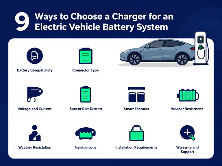
To successfully select a charger for an electric vehicle battery system, you must evaluate nine core engineering parameters: (1) Precise Chemistry & Cutoff Voltage Matching (aligning exact cell count and absorption thresholds for LiFePO4, Ternary Li-ion, or Lead-Acid); (2) Charging Algorithm & Multi-Stage Curve Control (mandating true CC/CV with calibrated zero-current termination rather than destructive trickle float voltages); (3) Amperage Sizing & C-Rate Optimization (balancing 0.2C to 0.3C charge velocity against internal resistance heating); (4) Active BMS Communication Architecture (integrating CAN bus 2.0B or RS485 telemetry for dynamic current throttling); (5) Thermal Dissipation & Ingress Protection (mandating IP65 to IP67 fully potted aluminum enclosures for onboard vehicle mounting); (6) Wide AC Input Tolerance & Active Power Factor Correction (PFC > 0.98) to prevent circuit breaker trips; (7) Heavy-Gauge Terminal Metallurgy & Interlock Sensing (specifying temperature-monitored Anderson or REMA connectors); (8) Comprehensive Hardware-Level Safety Protections (reverse polarity, short circuit, over-voltage, and hardware timing cutoffs); and (9) High-Frequency LLC Resonant Efficiency (>92%) to minimize operational utility waste. Sourcing directly from an established power electronics manufacturer like OHRIJA guarantees factory-calibrated charge curves and industrial-grade electrical safety.
Article Directory
- What Is an EV Battery Charger and How Does High-Frequency Conversion Work?
- Quick Summary Table: The 9 Core Selection Benchmarks
- 9 Ways to Choose a Charger for an Electric Vehicle Battery System Analyzed
- Featured Power Electronics Manufacturer: OHRIJA Industrial Solutions
- Direct Technical Comparison: Charging Topologies & Chemistries
- Pros and Cons of Dedicated High-Frequency Smart Chargers
- Who Needs a Specialized EV Battery Charger vs. Who Can Use Basic Supplies
- Costly Sourcing & Operational Mistakes to Avoid
- Essential Sourcing Checklist: Auditing an EV Charger Manufacturer
- Expert Engineering & Procurement Verdict
- Frequently Asked Questions
- Authoritative Regulatory & Electrical Standards
What Is an EV Battery Charger and How Does High-Frequency Conversion Work?
A specialized charger for an electric vehicle battery system is a closed-loop, switch-mode AC-to-DC power converter engineered to replenish electrochemical energy into a traction battery pack according to strict voltage and current profiles. In electric golf carts, neighborhood electric vehicles (NEVs), electric utility trucks, e-motorcycles, and industrial automated guided vehicles (AGVs), the charger serves as the primary barrier between volatile grid power and sensitive chemical cells.
Unlike basic linear power supplies that rely on heavy 50/60 Hz copper-wound transformers and lossy rheostats, modern industrial EV chargers employ high-frequency LLC resonant switching topologies operating at 100 kHz or higher. The conversion process moves through four distinct electrical stages:
- AC Rectification and Active Power Factor Correction (PFC): Incoming utility alternating current (85V to 265V AC) is rectified into high-voltage direct current. An active PFC boost converter shapes the input current waveform to match the AC sinusoidal voltage, eliminating reactive harmonic noise and achieving a power factor greater than 0.98.
- High-Frequency Inversion and Isolation: High-power MOSFETs or silicon carbide (SiC) switching devices invert the DC bus voltage into high-frequency alternating pulses. This AC waveform passes through a compact planar transformer that provides galvanic isolation exceeding 2,500V AC, protecting the vehicle chassis from high-voltage grid transients.
- Secondary Synchronous Rectification: High-speed Schottky or synchronous rectifier diodes convert the isolated high-frequency AC into stable, low-ripple DC output voltage matched to the pack chemistry.
- Microprocessor-Controlled Closed-Loop Regulation: An onboard 32-bit digital microcontroller continuously samples output voltage, shunt current, and thermal sensors at millisecond intervals, modulating pulse-width modulation (PWM) duty cycles to execute precise multi-stage charging algorithms.
From our experience across industrial fleet testing, using an uncalibrated bench supply instead of a dedicated charger for an electric vehicle battery system is a recipe for battery failure. Traction batteries do not absorb current linearly; their internal resistance shifts dramatically as state-of-charge (SoC) climbs. A high-grade charger dynamically regulates this boundary to deliver clean power without generating destructive heat.
Quick Summary Table: The 9 Core Selection Benchmarks
| Selection Pillar | Target Engineering Specification | Measured Technical Metric | Operational Failure Prevented | Commercial Value |
|---|---|---|---|---|
| 1. Voltage & Chemistry Match | Exact series count (e.g., 16S LiFePO4 = 58.4V cutoff) | Voltage regulation tolerance ±0.2V | Undercharging capacity loss or over-voltage cell venting | Maximizes daily usable driving range |
| 2. Charging Curve Profile | True CC/CV with hard cutoff vs. 3-stage lead-acid float | Termination current threshold < 0.05C | Electrolyte boiling in AGM; lithium cathode degradation | Extends battery cycle life by 2x to 3x |
| 3. Amperage & C-Rate | 0.2C to 0.3C optimal charge rate (e.g., 20A for 100Ah) | Current ripple < 3% RMS | Excessive internal cell heating and dendrite short-circuits | Prevents premature capacity fade |
| 4. BMS Communication | Isolated CAN bus 2.0B, RS485, or dry-contact enable | 125/250/500 kbps baud rate telemetry | Overcharging unbalance cells; false high-voltage trips | Synchronizes active cell balancing |
| 5. Ingress Protection (IP) | IP65 to IP67 fully potted aluminum alloy enclosure | Withstands high-pressure water spray & submersion | Internal circuit board corrosion and short-circuit fires | Allows permanent onboard vehicle mounting |
| 6. Input PFC & Efficiency | Active PFC > 0.98; conversion efficiency ≥ 92% | THD < 5%; universal 85V–265V AC range | Tripping facility breakers; excessive electrical utility waste | Cuts fleet operational electric bills |
| 7. Output Connectors | Industrial Anderson SB/PP, REMA, or custom multipin | Silver-plated copper contacts; 8 to 10 AWG leads | Terminal melting, arcing, and contact resistance drop | Guarantees low-resistance connection |
| 8. Safety Hardware Layer | Dual hardware over-voltage, reverse polarity, thermal cut | Hardware response time < 10 microseconds | Catastrophic reverse-hookup sparks and battery fires | Passes commercial workplace safety audits |
| 9. Thermal Management | Sealed die-cast heatsink; fanless natural cooling option | Operating ambient range -20°C to +55°C | Thermal throttling, shutdown, and premature capacitor dry-up | Maintains full output in hot warehouses |
9 Ways to Choose a Charger for an Electric Vehicle Battery System Analyzed
1. Match Exact Battery Chemistry and Absolute Cutoff Voltage
The single most dangerous assumption in electric vehicle maintenance is believing that a 48V charger works on any 48V battery pack. In modern vehicle design, 48V is merely a nominal marketing label. The actual maximum charging cutoff voltage depends entirely on chemical formulation and internal series cell count:
- 16S Lithium Iron Phosphate (LiFePO4): Nominal 51.2V; requires an exact absorption cutoff voltage of 58.4V (3.65V per cell).
- 13S Ternary Lithium-Ion (NCM/NCA): Nominal 48.1V; requires an exact cutoff voltage of 54.6V (4.20V per cell).
- 14S Ternary Lithium-Ion (NCM/NCA): Nominal 51.8V; requires an exact cutoff voltage of 58.8V (4.20V per cell).
- 48V Flooded Lead-Acid / AGM / Gel: Requires absorption voltages between 57.6V and 59.2V, followed by a continuous float stage at 54.0V.
If you connect a 58.8V NCM charger to a 13S pack, you will overcharge the cells past their safety boundary, leading to catastrophic thermal runaway. Conversely, if you use a 54.6V charger on a 16S LiFePO4 pack, the battery will never charge past 65% capacity, triggering chronic cell imbalance. For lithium iron phosphate conversions, always mandate a verified LIFEPO4 BATTERY CHARGER with voltage tolerances within plus-or-minus 0.2V.
2. Audit the Multi-Stage Charging Curve and Termination Algorithm
Battery chemistries require specialized thermodynamic charge profiles. Traditional lead-acid batteries demand a three-stage profile: Constant Current (Bulk), Constant Voltage (Absorption), and a perpetual Float stage to counteract internal self-discharge. Many lead-acid chargers also incorporate an equalization phase that spikes voltage up to 15.5V per 12V block to break up lead sulfate crystals on submerged plates.
If you subject a lithium pack to a charger with an equalization or float stage, you will destroy the cathode material. Lithium chemistries require a strict Constant Current / Constant Voltage (CC/CV) profile:
- Constant Current (CC): The charger pumps its maximum rated amperage into the pack while voltage climbs steadily from depleted state to cutoff threshold.
- Constant Voltage (CV): The charger locks voltage precisely at the maximum threshold (e.g., 58.4V) while current naturally tapers downward as cell potential equalizes.
- Hard Cutoff Termination: When current drops below the calibrated termination threshold (typically 0.02C to 0.05C, or roughly 1A to 2A), the charger must completely disconnect output. It must never float.
When maintaining legacy lead-acid vehicles, deploy a purpose-built LEAD ACID BATTERY CHARGER, and never mix algorithms between chemistries.
3. Size Output Amperage to the Pack C-Rate and Thermal Limits
Commercial users often demand the highest amperage charger available, assuming faster charging always translates to higher fleet efficiency. However, forcing excessive current into a battery pack accelerates lithium plating, increases internal resistance (IR) heating ($P = I^2R$), and shortens pack lifespan.
In most professional situations, we recommend sizing charger amperage between 0.2C and 0.3C of total pack capacity. For a standard 48V 100Ah golf cart battery, a 20A to 30A charger delivers the ideal balance, replenishing an 80% discharged pack in 3 to 4 hours without generating excessive heat. If your operation demands heavy-duty multi-shift turnaround requiring 0.5C charging (50A on a 100Ah pack), you must verify that the battery cells are rated for continuous fast-charging and that internal wiring harnesses can carry the current without resistive voltage drops.
4. Verify Active BMS Telemetry Integration (CAN Bus vs. Standalone)
In modern lithium-powered electric vehicles, the charger and the BMS must function as an integrated team. A standalone, uncommunicative charger pumps current blindly until its internal timer or voltage threshold is reached. If an individual cell within the pack drifts out of balance and spikes to 3.90V while the rest sit at 3.40V, an uncommunicative charger will keep pushing current, forcing the BMS to trip its high-voltage disconnect switch under full load.
Tripping a BMS under high charging current creates severe inductive voltage spikes that arc internal contactors and stress charger output capacitors. High-reliability commercial chargers incorporate an isolated CAN bus 2.0B or RS485 communication interface. Through CAN messaging, the BMS continuously broadcasts real-time parameters: maximum allowable charge current, individual cell temperatures, and pack state-of-charge. If cell temperatures climb past 50°C or a single cell nears its ceiling, the charger throttles current smoothly, preventing nuisance shutdowns.
5. Evaluate Ingress Protection (IP65/IP67) for Onboard vs. Offboard Mounting
Decide whether the charger will live on a workshop bench (offboard) or bolted permanently inside the vehicle chassis (onboard). Offboard chargers operate in relatively clean garage environments, allowing the use of budget-friendly fan-cooled enclosures with open ventilation slots.
Onboard chargers face brutal operating environments: gravel road vibrations, mud splashing, rainstorms, and high-pressure hose cleanups. Installing a ventilated fan-cooled charger inside a golf cart or utility vehicle chassis leads to rapid failure; road grit jams cooling fans, and puddle moisture corrodes internal surface-mount traces. For onboard vehicle applications, we recommend choosing a fully sealed WATERPROOF CHARGER rated IP65, IP66, or IP67. These units feature die-cast aluminum enclosures vacuum-filled with thermally conductive silicone or epoxy potting resin, protecting internal components against moisture, salt spray, and continuous mechanical shock.
6. Mandate Active Power Factor Correction (PFC > 0.98) and High Conversion Efficiency
Operating a fleet of 10 to 50 electric utility vehicles requires managing substantial electrical utility loads. Cheap, low-efficiency chargers draw distorted non-sinusoidal current from utility panels, yielding terrible power factor ratings (PFC ~ 0.65 to 0.75) and generating high Total Harmonic Distortion (THD > 30%). In commercial facilities, poor power factor causes neutral line overheating, nuisance breaker tripping, and commercial utility penalty charges.
Insist on chargers equipped with active Power Factor Correction achieving PFC ≥ 0.98 across universal input voltages (85V to 265V AC). Furthermore, evaluate electrical conversion efficiency. High-frequency LLC resonant designs deliver peak efficiencies between 92% and 95%. A 3% to 5% efficiency improvement across a 30-cart fleet running daily charging cycles saves thousands of dollars in utility expenses over a vehicle lifecycle.
7. Inspect Output Connector Metallurgy and Interlock Wiring
The cable connection between the charger and the vehicle chassis is a common mechanical failure point. Cheap chargers cut costs by using thin copper-clad aluminum (CCA) wire leads and unbranded molded plastic plugs. When passing 25A of continuous current through loose contact pins, terminal resistance climbs ($P = I^2R$), melting plastic housings and sparking battery terminals.
Demand genuine high-current terminal hardware:
- Silver-Plated Copper Contacts: Using authentic Anderson Powerpole, SB50, SB175, or REMA DIN connectors that maintain low contact resistance under thousands of insertion cycles.
- Vehicle Charge Interlock Sensing: Professional vehicle chargers include an auxiliary interlock signal wire. When the charger plug is inserted into the vehicle receptacle, the interlock circuit grounds the vehicle speed controller, mechanically preventing the driver from stepping on the accelerator pedal and tearing the charging cable off the wall.
- Heavy-Gauge Pure Copper Cabling: Sizing cables to 8 AWG or 10 AWG pure stranded copper to prevent resistive voltage drops along extended cord runs. Explore purpose-built hardware in our verified OUTPUT CONNECTOR catalog.
8. Require Multi-Layer Hardware Safety Protections
Never rely on software code alone to prevent battery fires. A firmware glitch in an unbranded charger can lock switching FETs in a closed state, pumping full line power into a fully charged battery. A commercial-grade charger must incorporate redundant, independent hardware-level protective circuits:
- Short-Circuit Protection: Immediate hardware shutdown within microseconds of positive and negative terminal contact, with automatic recovery once the fault is cleared.
- Reverse Polarity Protection: Prevents arcing and component destruction if an operator connects positive to negative, utilizing series MOSFETs or mechanical relays rather than blowing internal sacrificial fuses.
- Dual Over-Voltage Clamping: Secondary independent hardware comparators that shut down the PWM controller if voltage exceeds safe limits by even 1.5V.
- Internal Thermal Protection: Negative temperature coefficient (NTC) thermistors embedded into main heatsinks that automatically throttle output current if internal temperatures exceed 85°C, recovering once cooled.
9. Evaluate Fleet Scalability, Form Factor, and Total Cost of Ownership
When procuring charging equipment for commercial facilities, consider the total operational footprint. A heavy, bulky charger that requires two technicians to install complicates maintenance. Modular, stackable aluminum designs simplify mounting across utility beds, golf cart chassis, and industrial mobile equipment.
Review the comprehensive economics before signing purchase orders. An inexpensive $90 unbranded charger that fails after nine months, destroys a $1,500 lithium battery pack, or causes workplace downtime costs far more than a certified industrial unit. For micro-mobility and personal transport setups, review specialized lines such as our dedicated ELECTRIC BICYCLE CHARGER and precision ELECTRIC WHEELCHAIR CHARGER collections to ensure power electronics match your vehicle scale.
Manufacturer Spotlight: OHRIJA Industrial Battery Charging Solutions
Navigating the complex technical balance between battery chemistry, charging profiles, and commercial durability requires an asset-backed power electronics manufacturing partner. OHRIJA (Dongguan Hengruihong Technology Co., Ltd.) operates an advanced high-tech enterprise integrating research, engineering, and volume production in Dongguan, Guangdong.
| Corporate Engineering | Established in 2020; specialized high-frequency switch-mode power conversion R&D |
| Chemistry Coverage | Engineered platforms for high-rate LI ION BATTERY CHARGER, LiFePO4, AGM, and lead-acid battery packs |
| Specialized Vehicles | High-volume factory-direct supply of heavy-duty GOLF CAR BATTERY CHARGER units, utility vehicles, and AGVs |
| Power Electronics | Comprehensive development across POWER SUPPLY, switching adapters, and high-efficiency converters |
| Quality & Compliance | 100% full-load burn-in testing, CE, FCC, RoHS certifications, and custom CAN bus integration |
Procurement Recommendation: Review our complete commercial catalog on the OHRIJA battery charger store to source factory-direct, calibrated charging hardware built for demanding electric vehicle operations.
Direct Technical Comparison: Charging Topologies & Chemistries
| Charging Technology Class | Energy Efficiency | Weight & Form Factor | Chemical Compatibility | BMS Telemetry Support | Harsh Environment Suitability |
|---|---|---|---|---|---|
| High-Frequency Smart Resonant Charger (e.g., OHRIJA Industrial) | Exceptional (92% – 95%) | Compact & lightweight (Die-cast aluminum, 2–5 kg) | LiFePO4, Li-ion, AGM, Gel (MCU Calibrated) | Full isolated CAN bus 2.0B / RS485 communication | High (IP65 to IP67 fully potted sealed enclosures) |
| Legacy Ferroresonant / Transformer (Heavy Iron Core Chargers) | Poor (65% – 75%) | Extremely bulky and heavy (15–30 kg) | Flooded lead-acid only; destroys lithium cells | Zero communication; relies on voltage rise taper | Low (Open chassis; vulnerable to dust and moisture) |
| Unregulated Benchtop Power Supply (Generic DC Power Unit) | Moderate (80% – 85%) | Medium desktop benchtop chassis | Manual adjust; high risk of operator error | Manual monitoring only; zero BMS integration | Very low (Indoor lab use only; no vibration rating) |
| Standard Low-Cost Offline Switched (Plastic Enclosure Consumer) | Moderate (82% – 87%) | Lightweight plastic housing | Fixed single chemistry; basic analog cutoff | None; basic analog high-voltage threshold | Low (Ventilated cooling fan sucks in road moisture) |
Pros and Cons of Dedicated High-Frequency Smart Chargers
| Charging Hardware Architecture | Operational & Electrical Advantages | Engineering Limitations & Trade-Offs |
|---|---|---|
| Dedicated High-Frequency EV Charger (Smart Sealed Switch-Mode Unit) | Maximizes battery cycle life via precise multi-stage CC/CV curves. High conversion efficiency (>92%) lowers fleet electrical utility bills. Compact, lightweight footprint permits permanent onboard mounting. IP67 potted construction survives extreme moisture, mud, and vibration. CAN bus connectivity allows dynamic battery management communication. | Higher initial purchase price compared to generic non-smart supplies. Requires factory parameter matching for non-standard voltage setups. Requires planning for proper thermal mounting airflow across cooling fins. |
| Generic Multipurpose Power Supplies (Low-Cost Unregulated Converters) | Low initial purchase price from consumer retail channels. Adjustable voltage potentiometers on certain basic units. Widely available off-the-shelf for emergency bench testing. | Lacks automated cutoff algorithms; risks overcharging and cell fires. No vehicle interlock safety to prevent driving off while plugged in. Fragile construction; road vibration shatters internal solder joints. Zero communication with vehicle battery management systems. |
Who Needs a Specialized EV Battery Charger vs. Who Can Use Basic Supplies
Every commercial vehicle application demands an honest evaluation of operational duty cycles, electrical safety risks, and maintenance budgets. Investing in a high-grade smart charger is essential for professional fleets, while simpler hardware may suffice for low-risk testing.
Who Must Invest in a Dedicated Smart EV Battery Charger:
- Commercial Golf Cart & Resort Vehicle Fleets: Resorts, golf courses, and gated community shuttle fleets run continuous daily charge-discharge cycles. Installing a sealed, high-efficiency onboard charger ensures vehicles recharge overnight without tripping facility breakers or degrading expensive battery packs.
- Lithium Conversion Projects (Lead-Acid to LiFePO4): Upgrading an existing electric vehicle from heavy lead-acid to lithium iron phosphate requires replacing the legacy charger. Retaining an old transformer charger will ruin your new lithium pack within weeks.
- Industrial AGVs, Mobile Robots & Warehouse Tuggers: Automated warehouse vehicles demand fast opportunity charging and automated CAN bus handshake protocols to recharge safely without human supervision.
- Municipal Utility & Low-Speed Electric Vehicles (LSVs): Street-legal electric transport operating in rain, snow, and road salt environments requires the sealed durability of an IP67 waterproof charger.
Who Can Use Simpler Power Supplies:
- Electronics R&D Laboratories and Test Benches: If your team is running benchtop characterization on single battery cells under close human supervision, using an adjustable laboratory power supply allows precise manual voltage adjustments.
- Static Solar Energy Storage Walls: Stationary home battery banks that recharge via integrated solar charge controllers and hybrid inverters do not require ruggedized, vibration-proof EV chargers.
Costly Sourcing & Operational Mistakes to Avoid
Factory Floor Advisory: The costliest mistake fleet operators make is charging cold lithium batteries below freezing with an unmonitored charger. Forcing standard charging current into a lithium pack below 0°C (32°F) causes permanent lithium metal plating on the graphite anode, inducing internal micro-shorts that lead to spontaneous battery fires.
- Reusing Obsolete Lead-Acid Chargers on Lithium Conversions: When converting a golf cart from lead-acid to LiFePO4, operators often try to save money by keeping the old iron-core charger. Lead-acid chargers feature desulfation pulses and prolonged float stages that trigger lithium BMS safety shutoffs and cook cell electrolytes. Always replace the charger when switching chemistries.
- Mounting Fan-Cooled Chargers in the Direct Path of Road Spray: Installing an open-vent fan-cooled charger directly underneath an electric utility vehicle chassis invites road mud, gravel, and puddle water into high-voltage circuit boards. Fan-cooled units belong in clean, dry environments; vehicle chassis installations demand sealed, potted IP67 hardware.
- Ignoring AC Wall Receptacle Amperage Limits: Sourcing a powerful 48V 40A charger (drawing over 2,300W from the wall) and plugging it into a standard 110V 15A residential circuit will trip household breakers immediately. Ensure input power requirements match local electrical circuits, or select units with power factor correction and input current limiting.
- Using Undersized, High-Resistance Charging Cables: Running long, thin 14 AWG extension cords to an EV charger creates severe voltage drops and heat buildup. Under heavy current draw, undersized cords starve the charger of input voltage and create serious fire hazards. Always use heavy-gauge 10 AWG or 12 AWG extension cords rated for commercial loads.
Essential Sourcing Checklist: Auditing an EV Charger Manufacturer
Before issuing a formal Purchase Order or contracting an OEM power electronics manufacturer, verify these four essential engineering criteria with your technical team:
1. Verified Full-Load Burn-In and Thermal Testing Dossier
Inquire about the factory’s quality assurance testing protocols. Reputable manufacturers subject 100% of finished chargers to full-load burn-in testing inside high-temperature chambers (typically 40°C to 50°C for 2 to 4 hours) to eliminate infant mortality failures before shipment. Demand written confirmation of these testing procedures.
2. International Safety Certifications and File Numbers
Verify that the manufacturer holds active, verifiable safety listings matching your destination market:
- North America: UL 2202 (Standard for Electric Vehicle Charging System Equipment) or UL 1564 (Industrial Battery Chargers), accompanied by FCC Part 15 Class A/B electromagnetic compliance.
- European Union: CE certification covering the Low Voltage Directive (LVD 2014/35/EU) and Electromagnetic Compatibility Directive (EMC 2014/30/EU).
- Environmental Compliance: RoHS and REACH certifications confirming raw components are free of hazardous lead, cadmium, and toxic plasticizers.
3. Custom Firmware and Charging Curve Programming Capabilities
Ensure the manufacturer has in-house software engineering capabilities to customize CC/CV curves, taper thresholds, and CAN bus baud rates. If your project utilizes custom prismatic cell configurations (such as an uncommon 15S or 20S LiFePO4 arrangement), the supplier must be capable of flashing dedicated microcode to match your exact pack specifications.
4. Comprehensive Warranty Terms and Technical Support
Commercial equipment requires dependable warranty backing. Settle for nothing less than a 12 to 24-month replacement warranty on industrial charging hardware. Verify that the manufacturer maintains responsive technical support channels to assist with CAN bus communication integration and connector pinout diagnostics.
Expert Engineering & Procurement Verdict
In our professional assessment, treating an EV charging system as a secondary commodity is the leading cause of premature battery pack failure across commercial fleets and custom electric vehicles. Squeezing a few dollars out of your procurement budget by buying an uncertified, uncalibrated power converter will cost you thousands in destroyed battery cells, excessive downtime, and safety liability.
Selecting the right charger for an electric vehicle battery system requires disciplined engineering alignment. Match exact chemistry cutoff voltages down to fractions of a volt, enforce multi-stage CC/CV profiles with hard cutoffs, integrate active CAN bus communication with your BMS, and insist on sealed IP67 aluminum enclosures for onboard vehicle mounting. Sourcing certified power conversion hardware from experienced, asset-backed manufacturers like OHRIJA protects your battery investment, cuts operating costs, and delivers the reliable, safe performance your electric vehicles demand.
Frequently Asked Questions
Can I charge a LiFePO4 battery pack using a standard lead-acid battery charger?
No. Never charge lithium iron phosphate batteries with a lead-acid charger. Lead-acid algorithms feature trickle float modes and equalization stages exceeding 15.5V per 12V block, which damages lithium cathode crystal structures and triggers high-voltage cutoffs in battery management systems.
What is the ideal charging C-rate for commercial electric vehicle battery packs?
For commercial utility vehicles, golf carts, and delivery fleets, a charging rate between 0.2C and 0.5C provides the ideal balance between recharge speed and thermal preservation. For example, a 100Ah pack pairs best with a 20A to 30A charger, achieving full replenishment in 3 to 5 hours without accelerating dendrite growth.
Why is an onboard waterproof charger preferred over a portable benchtop charger?
An onboard waterproof charger rated IP65 to IP67 is hermetically potted with thermally conductive resin, allowing it to withstand road vibrations, puddle splashing, and pressure washing without internal component shorts, eliminating the need to haul external power supplies.
How does CAN bus communication improve electric vehicle charging safety?
CAN bus communication allows the charger to receive dynamic real-time commands directly from the battery management system (BMS), including individual cell temperatures, allowable current limits, and voltage thresholds, automatically throttling output when individual cells drift or overheat.
Authoritative Regulatory & Electrical Standards
- SAE International: SAE J2293 Energy Transfer System for Electric Vehicles – Functional Requirements and System Architectures
- Underwriters Laboratories (UL): Standard for Safety for Electric Vehicle Charging System Equipment (UL 2202 / UL 1564)
- International Electrotechnical Commission (IEC): IEC 61851 Electric Vehicle Conductive Charging Systems