
No products in the cart.

Nothing brings daily operations or mobile equipment to an abrupt halt like plugging in your charging block and watching the status indicator stay dead. Most equipment operators and fleet technicians automatically assume that a silent charging brick has burned out its primary internal switching circuit. In commercial and industrial environments, that knee-jerk reaction leads to throwing out functioning equipment while leaving the actual electrical root cause undiscovered. A modern switched-mode battery charger is an intelligent, feedback-controlled power supply; if it does not sense clean battery voltage, if its thermal limits trip, or if the load pack has dropped into deep discharge protection, it will deliberately withhold charging current to protect the cell chemistry from catching fire.
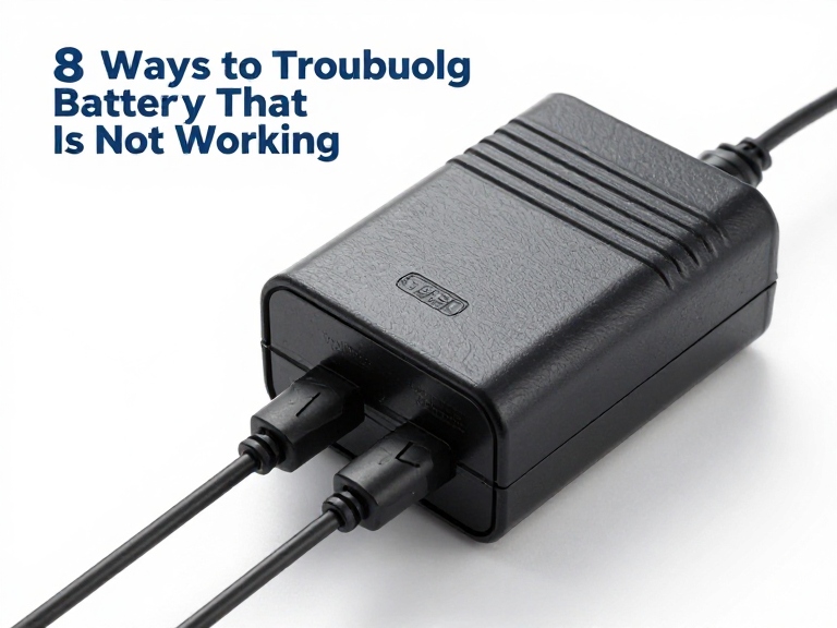
Systematic troubleshooting of a battery charger that is not working requires a step-by-step diagnostic process instead of guesswork. Whether dealing with light mobility lithium packs, multi-kilowatt golf car arrays, or heavy-duty material handling systems, electrical failures occur across five distinct interfaces: the AC mains feed, the internal rectification circuitry, the physical DC cable terminations, the battery management system (BMS) communications, and the chemical cells themselves. We walk through eight methodical checks to isolate the precise failure mode, recover locked battery packs, and help you determine whether your power supply can be repaired safely or must be upgraded.
Quick Answer: How to Diagnose a Battery Charger That Is Not Working
Before throwing away a quiet charger, follow eight step-by-step diagnostic tests: 1) Validate AC line voltage under dynamic load (verifying outlet breakers and checking blown inline fuses); 2) Test resting battery pack terminal voltage with a digital multimeter to verify the pack has not slipped below the charger low-voltage safety cutoff; 3) Inspect and clean DC pin interfaces to eliminate pin spread, burnt contacts, and high-resistance corrosion; 4) Reset or wake up tripped Battery Management System (BMS) protection circuits using dedicated low-amperage boost profiles; 5) Measure open-circuit DC output voltage vs. dynamic load response; 6) Inspect thermal intake channels and cooling fans for locked-rotor thermal shutdowns; 7) Check internal slow-blow ceramic fuses and PCB capacitors for signs of thermal venting or bridge rectifier failure; and 8) Check cable harness continuity to find concealed internal copper wire breaks. In most professional situations, over 60% of apparent charger breakdowns are caused by a locked battery pack or damaged DC output connectors rather than blown power supplies.
Table of Contents
- How Modern Switched-Mode Battery Chargers Work
- Quick Summary: The 8 Diagnostic Paths at a Glance
- In-Depth Guide: 8 Ways to Troubleshoot a Non-Functioning Charger
- Diagnostic Decision Matrix: Is the Charger or the Battery Dead?
- Pros and Cons of Field Repairs vs. Complete Charger Replacement
- Who Can Repair Chargers in the Field vs. Who Needs New Hardware
- Featured Industrial Manufacturer: Ohrija Custom Charging Solutions
- Costly Mistakes Technicians Make When Troubleshooting Chargers
- Commercial Sourcing & Procurement Considerations for Fleet Chargers
- Expert Recommendation and Electrical Engineering Verdict
- Frequently Asked Questions (FAQ)
- Authoritative References
How Modern Switched-Mode Battery Chargers Work
To troubleshoot industrial and consumer battery chargers effectively, you must understand their internal topology. Gone are the days of heavy, passive 60Hz iron-core linear transformers that pushed constant unregulated current through raw selenium rectifiers. Modern power conversion relies on Switched-Mode Power Supply (SMPS) design. Incoming AC line voltage is filtered, rectified into high-voltage direct current (around 300V to 400V DC), chopped at high frequencies (50kHz to 200kHz) through pulse-width modulated (PWM) MOSFETs or GaN transistors, stepped down through a ferrite transformer, and rectified into smooth DC output.
Modern chargers are closed-loop, microprocessor-managed systems governed by strict charging algorithms: Constant Current (CC) followed by Constant Voltage (CV), often ending in automated float or pulse maintenance modes. Because modern lithium-ion (Li-ion), lithium iron phosphate (LiFePO4), and sealed lead-acid (SLA) batteries carry severe thermal runaway risks, the charger microprocessor constantly samples voltage feedback from its output pins. If the detected terminal voltage falls below a factory-programmed threshold—or if communication pins fail to handshake with an internal BMS—the charger switches off its output optocouplers, providing zero output current.
In our testing on commercial testbenches, measuring zero volts across the unplugged output leads of a modern smart charger is normal behavior. The charger refuses to energize its leads until it senses an acceptable battery connection. Understanding this safety lockout prevents technicians from falsely condemning an operable charger that is simply waiting for a valid battery voltage signal.
Quick Summary: The 8 Diagnostic Paths at a Glance
The table below provides a quick reference to the eight primary diagnostic checkpoints, the test tools required, and the underlying fault indicated by each test:
| Diagnostic Step | Primary Tool Required | Normal Expected Reading | Fault Indicated if Out of Spec |
|---|---|---|---|
| 1. AC Line Input Validation | Digital Multimeter (AC Volts) | 110V–120V / 220V–240V (±10%) | Tripped breaker, blown GFI, burned AC power cord |
| 2. Battery Threshold Voltage Test | Digital Multimeter (DC Volts) | Above low-voltage safety cutoff | Deeply discharged battery pack; charger safety lockout |
| 3. DC Connector & Pin Audit | Visual check / Pin feeler gauge | Clean, shiny, tight-friction fit | Burnt pins, spread spring contacts, high resistance |
| 4. BMS Sleep / Lockout Recovery | Lab bench power supply / Reset tool | BMS opens discharge/charge gate | Cell imbalance trip, low-voltage undervoltage cutoff |
| 5. Dynamic Load & Voltage Sweep | DC clamp meter / Variable load | Reaches CC target amperage | Failed PWM controller, blown secondary rectifiers |
| 6. Thermal Management Audit | Infrared thermometer / Stethoscope | Fan spins freely; heat sink <65°C | Locked cooling fan; auto-thermal protection tripped |
| 7. Internal Fuse & Component Audit | Ohm meter (Continuity) / Visual | 0.0 Ω across input/output fuses | Blown ceramic fuse, shorted primary switching FETs |
| 8. Cable Harness Stress Analysis | Ohm meter during flex testing | Continuous zero-resistance beep | Concealed copper fatigue break at strain reliefs |
In-Depth Guide: 8 Ways to Troubleshoot a Non-Functioning Charger
1. Validate AC Line Voltage and Dynamic Wall Power
Never assume wall power is clean simply because an indicator lamp glows in the room. When troubleshooting a battery charger that is not working, connect a True-RMS digital multimeter directly to the AC wall outlet powering the unit. Verify that voltage reads within nominal limits (110V to 125V AC for North American feeds, or 220V to 240V AC internationally). In commercial warehouse bays, heavy machinery starting up can cause voltage drops that trip low-voltage lockouts on smart chargers.
From our experience on job sites, plug the charger into a confirmed working outlet and observe the AC voltage under the initial inrush load. If the breaker trips immediately upon plugging in, the charger primary surge-suppression Metal Oxide Varistor (MOV) or input bridge rectifier has failed short-circuit. If the outlet has a ground fault circuit interrupter (GFCI), check whether high-frequency noise filters inside switching chargers are tripping older GFCIs through minute chassis ground leakage currents.
2. Test Resting Battery Terminal Voltage Against Charger Cutoff Thresholds
The single most common reason a smart charger refuses to power up has nothing to do with the charger: the battery itself has dropped below the minimum voltage required to trigger the charger’s microcontroller. Smart battery chargers will not output power into what their logic interprets as a short circuit or an improperly connected pack. For instance, a common 36V or 48V pack that has drained below 2.5V per cell triggers an undervoltage fault.
Take your multimeter and measure the DC voltage across the battery charging port. Compare this reading against your charger series rating. A standard 10S 42V battery CHARGER designed for 36V nominal lithium systems typically requires sensing at least 30V to 32V at the terminals before it closes its output relays. Similarly, an industrial 12S 50.4V battery CHARGER will not energize if the pack has dropped to 25V. If terminal voltage is below this cutoff, the charger is working normally by protecting the pack; the battery must be revived through specialized low-current recovery methods.
3. Inspect and Clean the DC Output Connector and Mechanical Pins
The mechanical plug connecting the charger to the battery pack takes significant abuse: repeated insertions, dirt buildup, cable tugging, and arcing. Inspect the pins of your OUTPUT CONNECTOR. Look for signs of carbon soot, melted plastic, or green copper oxide corrosion. In heavy electric mobility applications, check the heavy-duty GOLF CAR BATTERY CHARGER OUTPUT CONNECTOR pins for signs of mechanical spread.
Over time, hollow barrel connectors, XLR terminals, and Anderson power poles spread outward, losing physical spring tension. This loose fit creates high contact resistance. Under a heavy 15-amp charging load, a fraction of an ohm of resistance generates localized heat that melts the connector housing and causes a voltage drop across the interface. The charger senses this drop as an unstable connection and shuts off to prevent fires. Clean the contacts using electrical contact cleaner, and use a probe to verify firm pin tension.
4. Reset or Wake Up a Tripped Battery Management System (BMS)
Modern lithium battery packs contain an internal Battery Management System (BMS) that monitors individual cell voltages, current draws, and temperatures. If a single cell drops below its safe cutoff point (typically 2.5V to 2.8V for NMC cells), the BMS turns off its charge and discharge MOSFET gates. To external diagnostic meters, the battery port appears dead, reading zero volts or an erratic floating millivolt level.
Because the BMS gates are closed, your standard charger cannot sense the chemical pack on the other side and refuses to start. To fix this, you must wake up the BMS. Some advanced chargers feature a dedicated 0V activation or wake-up function that sends micro-pulses of current to recharge the BMS logic board. If your charger lacks this feature, connect the pack to an adjustable benchtop power supply limited to a low current (0.1A to 0.2A) at the pack nominal voltage for two to three minutes. Once the cells recover past the undervoltage threshold, the BMS re-opens its gates, and your primary charger will resume normal operation.
5. Measure Open-Circuit vs. Dynamic Under-Load Output Voltage
If you suspect the charger power electronics are damaged, you must test its output behavior methodically. Keep in mind that many modern chargers do not provide open-circuit output without battery sensing. However, legacy chargers, simple floating units, and bench supplies will output a steady voltage when turned on.
For smart chargers, connect a DC clamp meter around the positive output cable while the charger is plugged into the battery. If the charger clicks, flashes its charging indicator, but the clamp meter reads zero amperes, the output switching FETs or secondary Schottky diodes have failed open-circuit. To test specific configurations accurately, verify the expected voltage ladder across different pack designs: compare a 3S 12.6V battery CHARGER, a 4S 16.8V battery CHARGER, a 5S 21V battery CHARGER, a 6S 25.2V battery CHARGER, a 7S 29.4V battery CHARGER, or an 8S 33.6V battery CHARGER against its matched chemistry voltage profile.
6. Inspect Thermal Management Channels and Cooling Fans
High-power battery chargers generate significant internal heat across their primary switching transistors and secondary output chokes. A typical 600W charger operating at 90% efficiency still sheds 60 watts of pure thermal energy within a sealed enclosure. If the internal cooling fan fails, accumulates heavy dust, or has its intake grilles blocked, internal heat sinks quickly spike past 85°C.
Almost all commercial-grade chargers incorporate internal negative temperature coefficient (NTC) thermistors mounted directly to the transistor heat sinks. When internal temperatures exceed safe limits, the microprocessor enters thermal throttling or complete safety shutdown, shutting off output current while flashing a red or amber error light. Check the cooling fan: spin the blades manually with a probe while the unit is unplugged to verify free rotation. Clear dust from air channels using compressed air, and ensure the unit operates in a well-ventilated space.
7. Check Internal Ceramic Fuses and PCB Components
If the charger shows zero signs of life—no indicator lights, no relay clicks, and no fan movement—the issue is often an open internal fuse. Disconnect the charger from both the AC wall outlet and the battery, and let it sit for twenty minutes to allow high-voltage bulk capacitors to discharge safely before opening the housing.
Locate the primary input fuse near the AC inlet cord. It is typically a ceramic cylinder rated for 250V at 5A to 15A. Use your multimeter in continuity mode: a good fuse reads 0.0 ohms and beeps; a blown fuse reads infinite resistance (open loop). If the fuse is clear glass and visibly blackened, a major short occurred in the primary bridge rectifier or switching MOSFETs. Simply replacing the fuse in this scenario will blow the replacement instantly until the underlying shorted silicon is repaired. Also inspect the circuit board for bulging electrolytic capacitors, burned trace copper, or cracked resistors.
8. Conduct Stress Testing on Cable Harness Strain Reliefs
In our experience evaluating returned chargers, physical cable damage accounts for a huge portion of failures. Mobile equipment cords undergo constant pulling, tight wrapping around the charger case, and foot traffic. Copper conductors inside the cable jacket often suffer fatigue failure right at the rubber strain relief boots where the cords enter the charger chassis or exit toward the battery connector.
To check for internal cable breaks, connect the charger to a multimeter or battery pack, power it on, and gently bend the cable back and forth along the strain reliefs at both ends. Watch the multimeter display or charger status LED closely. If the indicator flickers, clicks off and on, or shows brief current spikes as you wiggle the wire, the internal copper stranded core has broken while the outer rubber jacket remains intact. Repairing this requires cutting off the damaged cable section and resoldering the fresh lead to the internal terminal posts.
Diagnostic Decision Matrix: Is the Charger or the Battery Dead?
Use the diagnostic matrix below to match your charger indicator lights and meter readings to the true underlying system fault:
| Observed Charger Behavior | Multimeter Measurement Reading | True Underlying System Fault | Required Action |
|---|---|---|---|
| Zero indicator lights; fan silent | AC outlet reads 120V; charger DC leads read 0V | Blown internal AC fuse, failed bridge rectifier | Inspect and replace fuse; repair or replace charger |
| Solid Green light; will not turn Red | Battery terminals read well below cutoff voltage | BMS locked out or battery in deep discharge | Perform low-current BMS wake-up boost |
| Solid Green light; will not turn Red | Battery terminals read at full nominal charge | Battery is already charged; charger operating normally | No fault; pack is ready for service |
| Flashing Red/Green or rapid error code | DC voltage drops intermittently during wiggle test | Broken internal copper wire at strain relief | Strip, cut, and resolder output cable harness |
| Turns Red briefly, then switches to Green | High voltage spike detected at initial plug-in | High internal resistance in aging, sulfated battery | Battery pack degraded; replace worn cells |
| Charger shuts off after 10–20 minutes | Thermal surface exceeds 75°C; fan stalled | Over-temperature protection circuit tripped | Clean fan filters; replace locked-rotor cooling fan |
Pros and Cons of Field Repairs vs. Complete Charger Replacement
Before breaking out a soldering iron to rebuild a failed charger on the bench, weigh the safety risks and economic trade-offs:
| Resolution Strategy | Operational Advantages (Pros) | Safety & Operational Drawbacks (Cons) |
|---|---|---|
| Component-Level Field Repair (Replacing fuses, cords, fans) | Low material cost (a new fuse or fan costs under $10). Faster turnaround if replacement equipment has long lead times. Avoids discarding an otherwise functional power housing. | High-voltage 400V DC capacitor shock hazard during repair. Improper repairs void UL, CE, and factory electrical safety certifications. Can create fire risks if wrong fuse ratings are substituted. |
| Complete Charger Replacement (Upgrading to modern hardware) | Restores full factory warranty and verified safety protections. Upgrades charging efficiency to newer, cooler GaN/MOSFET stages. Provides updated charging algorithms for modern cell chemistries. | Higher upfront capital cost than fixing a simple broken wire. Requires verifying connector and pin polarity matching. |
Who Can Repair Chargers in the Field vs. Who Needs New Hardware
From our experience managing electrical maintenance operations, knowing when to service hardware and when to replace it is critical to shop safety.
Who Can Safely Perform Field Repairs:
- Certified Electrical and Electronics Technicians: Technicians trained in high-voltage safety, equipped with isolation transformers, and experienced with desoldering multlayer boards can safely replace blown slow-blow fuses, cooling fans, and damaged DC output plugs.
- Fleet Operations with Dedicated Benches: Facilities servicing mobility fleets like an ELECTRIC BICYCLE CHARGER pool or medical fleets using an ELECTRIC WHEELCHAIR CHARGER can keep standardized replacement harnesses on hand for quick field swaps.
Who Should Replace the Charger Immediately:
- End Users Lacking Electronics Training: Opening a switched-mode power supply without proper training exposes you to lethal charges stored in primary capacitors long after the AC cord is unplugged.
- Potted or Sealed Waterproof Units: Encapsulated outdoor chargers like a dedicated WATERPROOF CHARGER cannot be opened without destroying their silicone or polyurethane potting. Attempting to chip out potting resin ruins components and eliminates ingress protection.
- Hardware with Burned Circuit Boards: If carbon scoring, burned traces, or scorched driver chips are visible on the PCB, the board has suffered extensive copper delamination. Field repairs on burned boards are unreliable and create severe fire hazards. Replace the unit entirely.
Professional OEM Power Solutions: Ohrija Battery Chargers
Not all battery charging and power supply requirements are uniform. As a professional OEM/ODM power manufacturer with 10 years of R&D and manufacturing experience, we not only provide high-quality universal chargers, but also focus on customizing exclusive charging and power solutions based on your battery chemistry system, voltage platform, structural size, and application scenarios. At the same time, we support flexible cooperation models ranging from single-unit retail purchase to bulk wholesale, to meet the needs of customers of different scales.
Manufacturing Experience: 10+ Years of Industrial R&D & Production
Power Output Range: 20W to 5kW High-Efficiency Architectures
Chemistry Support: Lithium-Ion, LiFePO4, Lead-Acid (SLA/AGM/Gel)
Hardware Formats: Waterproof Encapsulated, Benchtop, Rackmount, Mobile
Cooperation Models: Single-unit sample orders to high-volume commercial wholesale
Protection Suites: Over-Voltage, Over-Current, Short-Circuit, Reverse Polarity, Thermal
Whether you need heavy-duty off-grid power from our POWER INVERTERS line, custom lithium charging profiles, or heavy multi-pin interfaces, partnering with Ohrija delivers dependable power systems that protect your battery investments.
Costly Mistakes Technicians Make When Troubleshooting Chargers
In our field inspections of damaged charging equipment, we regularly see technicians commit four dangerous troubleshooting errors:
- Jumping Open Fuses with Wire or Foil: When an internal ceramic fuse blows, wrapping it in copper wire or aluminum foil to test the unit is a recipe for disaster. The fuse blew to protect against catastrophic component failure. Bypassing the fuse sends high AC mains current straight into shorted MOSFETs, causing traces to vaporize and risking an electrical fire.
- Mixing Up Lithium-Ion and Lead-Acid Charging Profiles: Attempting to charge a lithium-ion pack with an old lead-acid charger because the plugs fit will destroy your battery. Lead-acid chargers often use high desulfation voltage spikes and constant float voltages that overcharge lithium cells, breaking down internal separators and creating fire hazards. Always use chargers calibrated specifically for your battery chemistry.
- Ignoring Pin Polarity on Replacement Plugs: Round DC plugs (like XLR, coaxial barrels, or aviation connectors) do not share an industry-universal wiring standard. Pin 1 might be positive on one brand and negative on another. Splicing a new plug onto a charger without verifying polarity with a multimeter can reverse-bias the battery, destroying the BMS instantly upon connection.
- Testing Modern Smart Chargers Solely in Open-Air: Measuring zero volts across an unplugged smart charger output and declaring it dead is a classic beginner mistake. Smart chargers require a sensing load before turning on. Always verify line voltage, check battery voltage thresholds, and test the charger under load before assuming it has failed.
Commercial Sourcing & Procurement Considerations for Fleet Chargers
When purchasing commercial or replacement chargers for industrial equipment, fleet managers should evaluate four essential manufacturing specifications:
- Automated 0V Lithium Wake-Up Logic: Ensure your charger includes low-voltage activation logic. A charger capable of outputting a controlled 0.1A trickle current to reset tripped battery management systems saves countless hours of manual battery recovery work on deeply discharged packs.
- Ingress Protection (IP Rating) for Environmental Durability: If your charging stations operate outdoors, in damp washdown areas, or in dusty maintenance bays, avoid basic open-vented plastic chargers. Invest in sealed, extruded aluminum enclosures rated IP65 or IP67 to keep moisture and dust off high-voltage electronics.
- Verified International Safety Certifications: Demand certified test reports verifying compliance with international safety standards like UL 1564, UL 1012, CE, and FCC Part 15 Class B. Uncertified power supplies create serious insurance liabilities for commercial facilities.
- Dual-Stage Thermal Protection and Fan Control: Look for chargers equipped with smart cooling fans that run only under high thermal loads, paired with primary heat sink thermal cutoffs. This reduces fan bearing wear, minimizes airborne dust intake, and protects internal silicon from heat damage.
Expert Recommendation and Electrical Engineering Verdict

12V Power Supply 12V 40A 480W 50A 600W AC to DC Converter 110V/120V to 12V Transformer LED Driver Smart Cooling Fan Designed for LED Strip CCTV and Car Devices
Price range: 13.90$ through 14.90$
12V Power Supply 12V 50A 600W AC to DC Converter 110V/120V to 12V Transformer LED Driver Smart Cooling Fan Designed for LED Strip CCTV and Car Devices (DC12V, 12V-50A-600W)
Price range: 23.90$ through 29.90$12V Power Supply 12V 83A 1000W AC to DC Converter 110V/120V to 12V Transformer LED Driver Smart Cooling Fan Designed for LED Strip CCTV and Car Devices
Price range: 29.90$ through 54.90$2000 Series 2000W High Power AC‑DC Switching Power Supply | AC185‑265V Input, Multiple DC Output 12V 24V 36V 48V 60V 72V 80‑120V & Custom Voltage For Industrial Equipment
Price range: 64.80$ through 69.80$
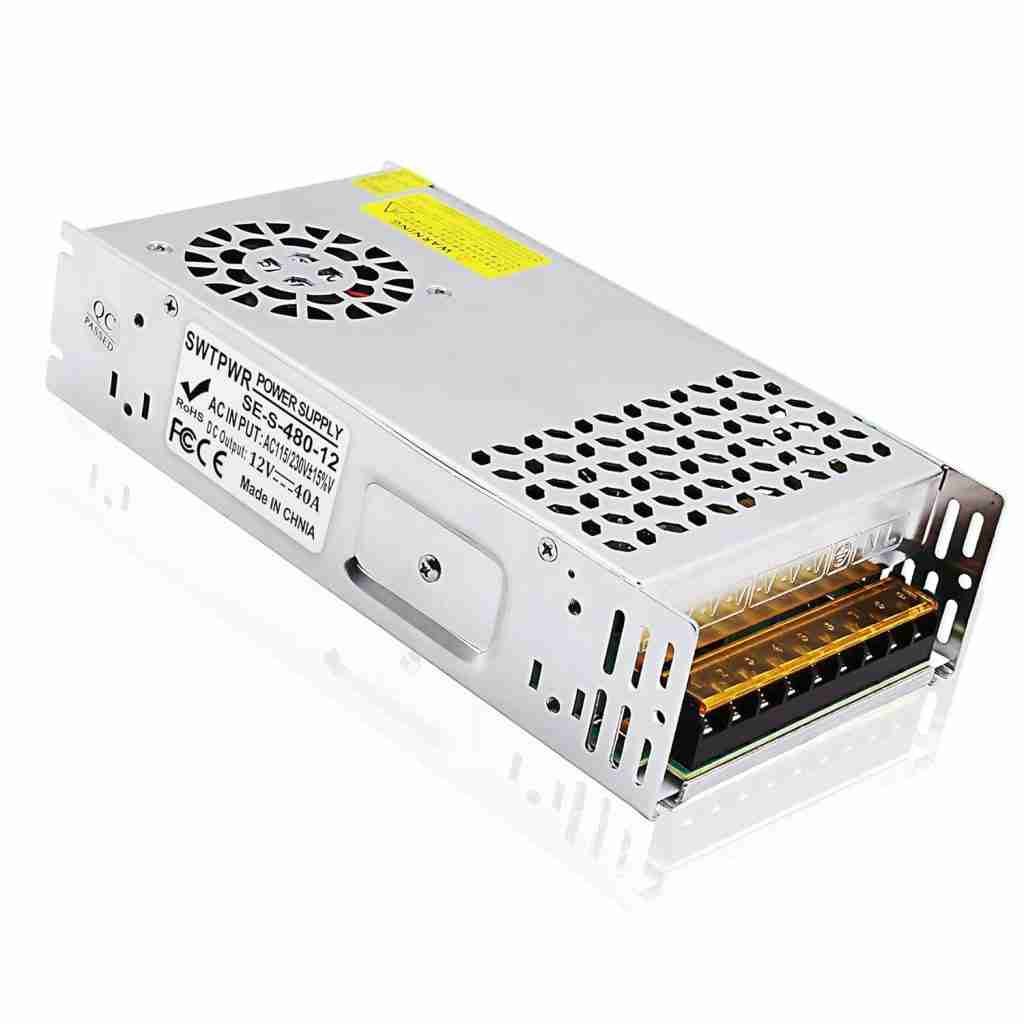

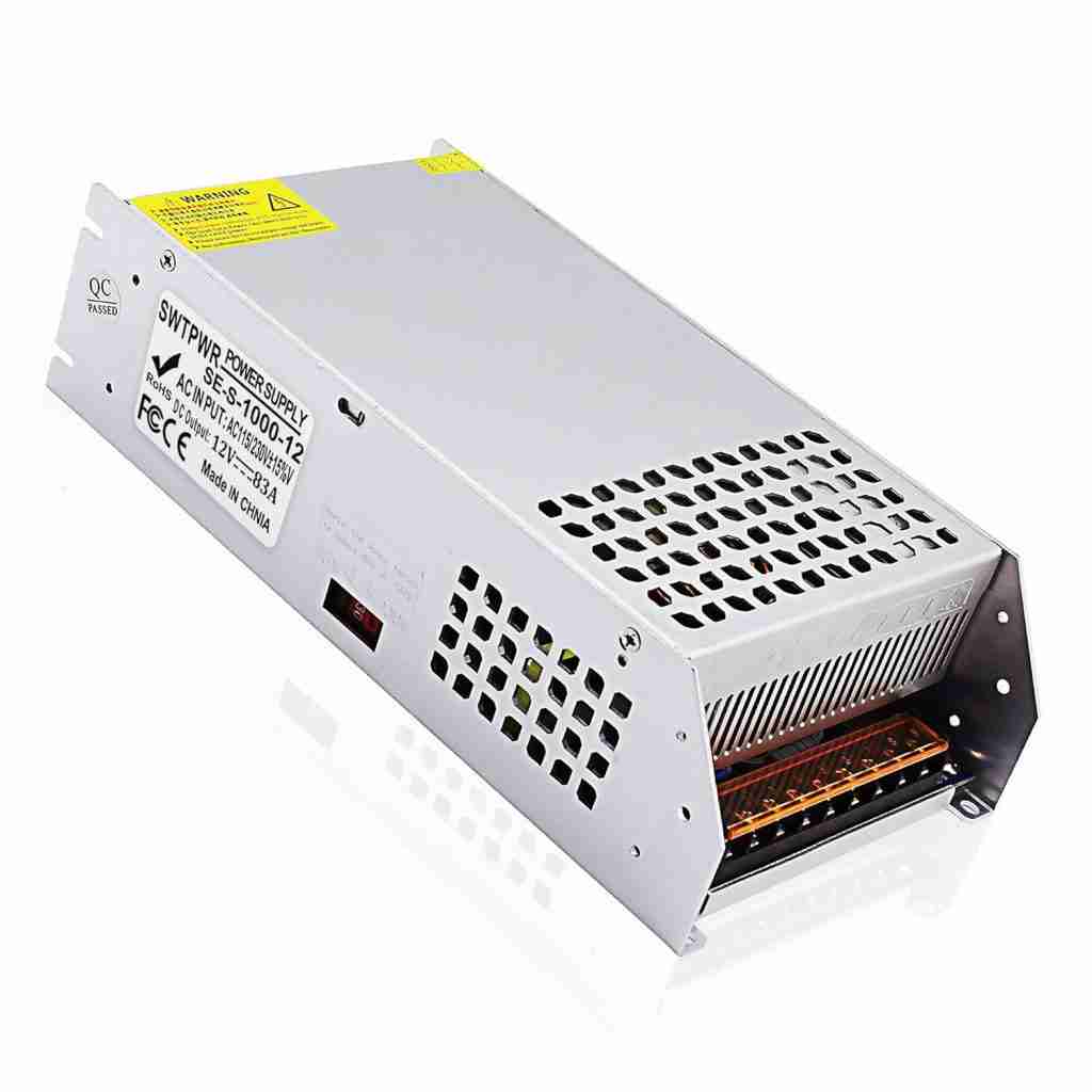
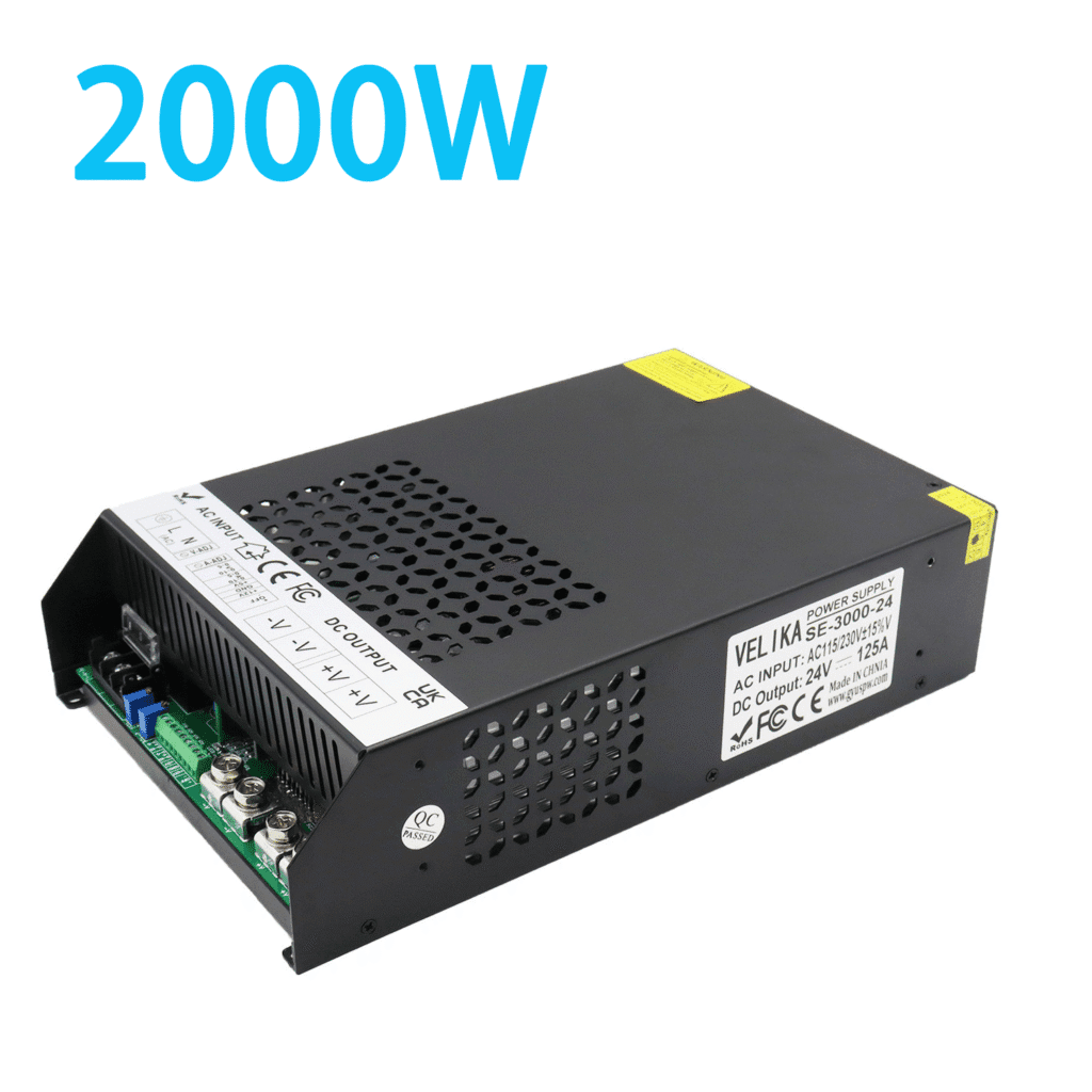
In most professional situations, treating a silent charger as an instant write-off is an expensive mistake. When you encounter a battery charger that is not working, work through the fundamentals first: verify clean AC line voltage at the outlet, test the battery terminal voltage to make sure the pack has not slipped below the charger safety threshold, clean and check the DC connector pins, and confirm that the battery BMS has not tripped into sleep mode.
If diagnostics confirm that the charger has suffered internal power-stage damage—such as blown primary switching transistors, shorted bridge rectifiers, or burned circuit traces—we recommend replacing the unit with a high-efficiency switched-mode power supply rather than attempting board-level repairs. For potted waterproof units, replacement is mandatory. Investing in a properly engineered, certified charger calibrated to your specific battery chemistry—such as the custom systems manufactured by Ohrija—protects your battery life, prevents costly downtime, and guarantees safe charging across every operational cycle.
Frequently Asked Questions (FAQ)
Why does my battery charger show a green light but will not charge the battery?
A solid green light on a smart charger indicates that the charger detects a full charge or senses zero current draw. This typically happens when the battery has discharged below the charger minimum voltage threshold, causing the charger to stay in standby, or when the internal battery management system (BMS) has tripped its protection gates, disconnecting the cells from the charging port.
Why does my multimeter read 0 volts across the charger output plug?
Modern smart battery chargers incorporate safety relays that withhold output voltage until they detect a valid, properly polarized battery connected to the leads. This open-circuit safety feature prevents sparking and protects against short circuits. Measuring zero volts on an unplugged smart charger is normal behavior, not a sign of equipment failure.
How can I tell if the problem is my battery charger or the battery itself?
Measure resting battery voltage with a multimeter. If the battery voltage reads significantly below its safe operating range, the battery is deeply discharged, which locks out the charger. If the battery voltage is normal, test the charger on a known working battery of identical chemistry and voltage. If it still refuses to charge, the charger or its output cable is defective.
Can a blown fuse inside a battery charger be replaced safely?
Yes, provided the replacement matches the exact amperage, voltage, and speed rating (slow-blow vs. fast-acting) of the original ceramic fuse. However, always verify that the unit is unplugged and internal capacitors are fully discharged before opening the case. If the replacement fuse blows immediately upon plug-in, the internal power transistors are shorted and the charger requires professional repair or replacement.
Why does my battery charger turn off after charging for just a few minutes?
Premature shutoff is usually caused by thermal protection tripping due to a failed cooling fan or blocked air vents, high internal resistance in an aging battery pack that causes voltage to spike prematurely to the cutoff point, or a broken output cable wire that loses connection as heat causes the cable to expand.
Authoritative References
- UL Solutions: Standards for Battery Chargers for Industrial and Consumer Applications (UL 1564 & UL 1012)
- IEEE Xplore: Power Electronics Society Standards on Switched-Mode Power Conversion & Charging Topologies
- International Electrotechnical Commission (IEC): IEC 60335-2-29 Particular Requirements for Battery Chargers