
No products in the cart.

Treating high-voltage switch-mode power supplies like dumb extension cords is an expensive habit in industrial maintenance, fleet electrification, and private workshop operations. Facility managers and electric mobility operators routinely obsess over battery pack health, thermal runaway limits, and cell balancing software, yet toss their heavy-duty chargers onto damp garage floors, wrap DC cables tightly around sharp metal heat sinks, and ignore cooling fan exhaust vents caked with conductive airborne dust. A modern smart charger is not a passive block of copper; it is an active power conversion system built with sensitive microcontrollers, high-frequency pulse-width modulation (PWM) switching MOSFETs, ultra-low ESR electrolytic capacitors, and optocouplers executing precise constant-current/constant-voltage (CC/CV) charge algorithms. Neglecting the charger directly threatens the battery pack it feeds.
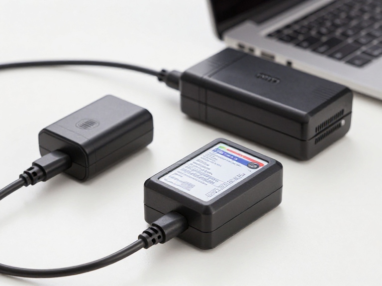
Navigating the operational discipline of maintaining battery chargers demands an understanding of electrical degradation, component thermal fatigue, and environmental exposure. When a charger operates in dusty or humid environments without inspection, output voltage calibration drifts. A drift of merely 0.5 volts on a high-voltage lithium array can cause battery management systems (BMS) to trigger over-voltage fault shutdowns, undercharge cells to reduce range, or force lithium-ion packs into dangerous overcharge territory. In our testing across workshop benches and industrial charging stations, following structured maintenance protocols prevents sudden component failure and extends charger operating life beyond a decade. We analyze nine essential maintenance and storage practices to protect your hardware investment, maintain output precision, and ensure safe charging cycles across lithium-ion, LiFePO4, and lead-acid installations.
Quick Answer: How to Store and Maintain Industrial Battery Chargers
Properly maintaining battery chargers requires disciplined environmental isolation, thermal management, and electrical verification across nine critical operational areas: 1) Store in a climate-controlled, non-condensing environment maintaining 40% to 60% relative humidity and temperatures between 15°C and 25°C; 2) Clear forced-air cooling vents and internal fan blades bi-annually using dry, oil-free compressed air under 30 PSI to prevent MOSFET thermal shutdown; 3) Inspect DC output cables and connector terminals for contact pitting, fret corrosion, and wire strain fatigue; 4) Verify CC/CV output voltage calibration annually using a calibrated true-RMS digital multimeter; 5) Eliminate cable-wrapping strain by using loose, 12-inch circular figure-eight loops to protect internal wire cores from copper strand breakage; 6) Power down using sequential disconnect protocols (mains AC supply disconnected before battery DC terminals); 7) Protect switch-mode power supply (SMPS) internal components from conductive airborne metal particles and corrosive battery acid outgassing; 8) Perform dielectric insulation checks (Hi-Pot) on legacy units; and 9) Exercise idle electrolytic capacitors periodically with a 30-minute unloaded power cycle every six months to prevent dielectric breakdown. In most professional situations, annual terminal cleaning and airflow clearing eliminate over 80% of premature field breakdowns.
Table of Contents
- The Engineering Breakdown: How Switch-Mode Battery Chargers Degrade
- Quick Summary: The 9 Charger Maintenance Tips at a Glance
- In-Depth Guide: 9 Tips for Storing and Maintaining Battery Chargers
- Maintenance Strategy Matrix: Reactive vs. Preventative vs. Overhaul
- Pros and Cons of Preventative Charger Maintenance Programs
- Who Needs Rigorous Maintenance Schedules vs. Casual Plug-and-Play Users
- Featured Industrial Manufacturer: OHRIJA High-Voltage Charging Systems
- Costly Mistakes Operators Make When Handling Battery Chargers
- Essential Sourcing and Hardware Selection Considerations
- Expert Recommendation and Electrical Management Verdict
- Frequently Asked Questions (FAQ)
- Authoritative References
The Engineering Breakdown: How Switch-Mode Battery Chargers Degrade
To understand the necessity of maintaining battery chargers, technicians must evaluate what happens inside a switch-mode power supply (SMPS) chassis during high-amperage operation. Unlike vintage transformer-rectifier units that relied on heavy iron cores and crude diode bridges, modern smart chargers convert incoming 110V/220V alternating current (AC) into smooth direct current (DC) using high-frequency switching circuits operating between 50 kHz and 200 kHz. This architecture allows compact form factors and high electrical efficiency exceeding 92%, but it relies heavily on sensitive components.
The primary point of physical wear in an SMPS is the electrolytic filter capacitor bank. Electrolytic capacitors contain liquid or gel-state electrolytes separated by thin aluminum oxide dielectric layers. Under normal operation, internal ripple currents and ambient heat cause the liquid electrolyte to slowly diffuse through the end-seals over thousands of operating hours. If a charger operates with clogged air vents, its internal ambient temperature can rise by 20°C. According to the Arrhenius rule of chemical kinetics, every 10°C increase in operating temperature cuts electrolytic capacitor lifespan in half. As capacitors degrade, equivalent series resistance (ESR) climbs, output voltage ripple surges, and high-frequency noise feeds directly into the battery pack, confusing sensitive BMS voltage monitors.
In our testing across industrial chargers, electrical connector oxidation represents the second major failure pathway. High-current charging connectors (such as Anderson Powerpole, REMA, XLR, or aviation screw plugs) undergo micro-arcing during live disconnections. This arcing strips away micro-inches of silver or tin plating, exposing raw brass or copper to ambient moisture. The resulting copper oxide increases terminal resistance, causing the charging plug to generate heat under continuous 15A to 30A loads, melting plastic housings and causing voltage drop errors that fool the charger into prematurely terminating its constant-current bulk phase. Proper maintenance prevents these failure loops before they damage connected battery packs.
Quick Summary: The 9 Charger Maintenance Tips at a Glance
The table below provides a quick operational reference to the nine maintenance practices, defining their technical execution, inspection intervals, and the specific failure modes they prevent:
| Maintenance Checkpoint | Recommended Frequency | Primary Technical Action | Critical Failure Mode Prevented |
|---|---|---|---|
| 1. Climate-Controlled Storage | Continuous (Between cycles) | Maintain 15°C–25°C, < 60% non-condensing RH | PCB copper trace corrosion, internal short circuits |
| 2. Forced-Air Cleaning | Bi-annually (Monthly in dirty shops) | Blow out heatsinks with clean compressed air < 30 PSI | MOSFET thermal runaway, fan motor bearing seizure |
| 3. Connector Deoxidation | Quarterly | Clean contact blades with electrical contact cleaner | Terminal melting, voltage drop errors, plug arcing |
| 4. Output Voltage Calibration | Annually | Measure floating/cutoff voltage with true-RMS DMM | Battery overcharging, BMS premature cutoff faults |
| 5. Cable Strain Relief | Daily / Every pack-down | Coil cords in loose figure-eight loops; no tight bends | Internal copper conductor shearing, short-circuit sparks |
| 6. Sequential Disconnection | Every charging operation | Isolate AC mains supply before unplugging DC battery lead | Connector contact pitting from inductive back-EMF arcing |
| 7. Environmental Isolation | Continuous | Isolate charger from flooded battery acid fumes & metal shavings | Acidic corrosion of solder joints, explosive gas ignition |
| 8. Enclosure & Ground Inspection | Annually | Test chassis ground continuity (< 0.1 ohm) and shell seals | Operator electric shock hazard, ground-fault tripping |
| 9. Electrolytic Reform Cycling | Every 6 months (Idle inventory) | Energize charger unloaded for 30 minutes on AC power | Capacitor dielectric breakdown during sudden initial load |
In-Depth Guide: 9 Tips for Storing and Maintaining Battery Chargers
1. Enforce Climate-Controlled, Non-Condensing Storage Parameters
The storage environment directly influences internal component longevity. Storing an industrial battery charger in an unheated outdoor shed, a damp commercial basement, or the open bed of a service truck exposes internal electronics to destructive diurnal temperature swings. As warm, humid daytime air transitions to cold night temperatures, air reaches its dew point, forming micro-condensation droplets across internal circuit boards.
This moisture combines with ambient ionic dust, bridging surface-mount components (SMD) on the circuit board. The resulting galvanic corrosion slowly eats through fine copper PCB traces and causes catastrophic short circuits when the unit is powered up. Store battery chargers on raised shelving inside a clean, dry room maintaining 15°C to 25°C (59°F to 77°F) and a relative humidity strictly below 60%. If hardware must sit idle for months during seasonal shutdowns, seal the charger inside a moisture-barrier bag packed with industrial desiccant clay packs.
2. Clean Forced-Air Vents and Heatsinks with Dry Compressed Air
High-wattage smart chargers generate substantial internal heat, particularly across power-factor correction (PFC) inductors, high-voltage switching MOSFETs, and secondary rectification diodes. To keep compact aluminum chassis cool, internal variable-speed brushless DC fans continuously pull high volumes of ambient air across extruded aluminum heatsinks.
Over months of workshop operation, that airflow pulls in shop dust, lint, animal hair, and airborne particulate matter. This debris blankets internal heatsink fins, acting as a thermal blanket that prevents heat dissipation. In our testing on service benches, clearing internal heatsink passages with dry, clean compressed air (regulated strictly below 30 PSI to avoid damaging delicate fan blades) immediately lowers internal operating temperatures by 12°C to 18°C. Never use liquid solvents or tap water to clean charger vents; use a soft, dry anti-static brush paired with low-pressure air, holding the fan blades steady with a plastic probe to prevent back-spinning current from damaging the motherboard fan header.
3. Inspect and Deoxidize DC Output Terminals and Pins
The physical connector joining the charger to the battery pack handles severe mechanical and electrical stress. Plugs are dropped onto concrete, kicked across garage bays, and subjected to repetitive insertion friction. Over time, terminal contacts accumulate copper oxide films, grit, and road grime, increasing contact resistance exponentially ($P = I^2 R$).
At high charging currents—such as running 20A through a heavy-duty pack—a tiny 0.05-ohm contact resistance produces 20 watts of localized thermal dissipation directly inside the plastic plug housing. This heat softens the terminal housing, degrades contact spring tension, and creates intermittent connections. Inspect contact blades quarterly. Spray connectors with residue-free electrical contact cleaner, use a micro-abrasive contact burnishing tool to strip away dark oxidation, and apply a micro-film of synthetic dielectric grease to prevent atmospheric corrosion on mating silver pins.
4. Verify CC/CV Output Voltage Calibration Annually
A smart charger’s internal voltage divider resistors and precision voltage reference diodes experience subtle resistance drift over operating years due to thermal cycling. In lithium-ion and lithium iron phosphate (LiFePO4) systems, voltage precision is non-negotiable. For example, charging a 16S LiFePO4 bank demands an exact termination cutoff voltage of 58.40 volts (3.65V per cell); if calibration drifts upward by merely 1.0%, output voltage reaches 59.0 volts, triggering high-voltage alarms on connected management systems or causing stress on delicate cell chemistries.
Once per year, verify your charger’s true cutoff voltage using a calibrated 4.5-digit true-RMS digital multimeter. Measure open-circuit voltage, then monitor the transition from constant current to constant voltage as the battery tops off. If your fleet deploys high-voltage packs—such as high-series commercial installations running a 14S 58.8V battery CHARGER, a 15S 63V battery CHARGER, or a heavy-duty 16S 67.2V battery CHARGER—even slight calibration drift creates noticeable cell balance discrepancies. Chargers featuring internal precision potentiometer trims should be adjusted by qualified technicians, while sealed units showing significant drift should be retired from service.
5. Implement Safe Cable Management and Strain Relief Routines
The most common physical failure point on portable chargers is cable strain fatigue directly adjacent to the molded plastic strain relief boot. When operators pack up gear, they frequently wrap heavy-gauge DC cables tightly around the metal charger housing. This tight wrapping forces internal multi-strand copper conductors against sharp aluminum chassis corners under tension.
Over repeated coiling cycles, individual copper strands shear within the PVC or silicone insulation jacket. Eventually, the effective wire cross-section shrinks, generating dangerous hot spots under high current loads, or sheared strands puncture the insulation jacket to cause dead short-circuits. Train operators to wind charging cables in loose, relaxed figure-eight loops or circular coils with diameters of at least 10 to 14 inches, securing them with velcro straps. Never allow the weight of the charger to hang suspended by its power cables from wall outlets.
6. Enforce Sequential Disconnection to Eliminate Contact Arcing
Disconnecting a charging system under full load is an easy way to cause connector erosion. When a charger pushes 15 to 30 amps into a battery pack, breaking the DC connection mid-charge causes an inductive voltage spike as magnetic fields collapse across internal filter chokes. This spike jumps across the separating contact pins as a hot electric arc.
This electrical arc vaporizes micro-layers of conductive plating, leaving jagged carbon pitting on the contact pins. After a dozen hot disconnects, the damaged contacts generate high electrical resistance. Establish a strict operating procedure: always shut off or isolate the AC mains supply first (via the power switch or wall receptacle), allow the internal filter capacitors to bleed down for two seconds, and only then disconnect the DC plug from the battery terminals. When reconnecting, reverse the sequence: plug into the battery first, then connect and energize the AC supply to prevent initial inrush sparking.
7. Isolate Chargers from Acid Outgassing and Airborne Metal Dust
Where you place a charger during operation dictates what enters its cooling vents. In mixed workshops, chargers are often mounted right next to metal grinders, chop saws, or machining lathes. Centrifugal fans pull airborne steel, aluminum, and brass grinding dust directly into the charger chassis. These metallic particles settle across high-voltage traces on the circuit board, causing explosive short-circuits across primary switching MOSFETs.
Similarly, operating chargers directly above flooded lead-acid batteries creates chemical hazards. During absorption and equalization charging phases, flooded lead-acid batteries release hydrogen gas mixed with acidic sulfuric acid vapor. If an active charger draws this acid mist through its cooling vents, the vapor strips the solder mask and corrodes copper traces within weeks. Always locate chargers at least four to six feet away from open battery vents, preferably mounted horizontally on dedicated racking in clean, ventilated air corridors.
8. Inspect Chassis Structural Sealing and Ground Continuity
Industrial shop floors expose equipment to physical impacts, tool strikes, and vibration. A damaged aluminum or steel chassis compromises ingress protection against splashing fluids and creates severe electrical shock hazards for operators.
Annually inspect the charger’s physical casing: confirm that case screws remain tight, rubber feet are intact, and silicone gasket seals around cable entry glands have not split. Crucially, verify safety grounding integrity: use a low-resistance ohmmeter to measure continuity between the ground pin on the AC input plug and the bare metal chassis exterior. Ground resistance must measure strictly below 0.1 ohms under IEC 60335 standards to ensure that internal primary insulation faults trip branch circuit breakers instantly rather than electrifying the metal case.
9. Reform Electrolytic Capacitors During Prolonged Idle Storage
When switch-mode battery chargers sit unpowered on warehouse shelves for twelve to twenty-four months, their internal aluminum electrolytic capacitors undergo chemical de-passivation. Without an active polarization voltage across the capacitor plates, the microscopic aluminum oxide dielectric insulating layer slowly dissolves into the liquid electrolyte.
If an operator takes a charger that has sat idle for two years and connects it to maximum battery loads, the sudden high voltage across the unformed dielectric layer causes high leakage currents, rapid internal gas generation, and potential capacitor venting. To prevent this, implement a capacitor exercising routine: every six months, pull idle chargers from inventory, plug them into AC mains power with no battery load attached, and allow them to run idle for thirty to forty-five minutes. This low-stress idle voltage safely re-forms the aluminum oxide dielectric layer, keeping internal capacitors ready for dependable high-load service.
Maintenance Strategy Matrix: Reactive vs. Preventative vs. Overhaul
To help guide your facility’s maintenance program, the matrix below compares the operational, financial, and reliability profiles of the three primary equipment management strategies:
| Management Approach | Labor & Inspection Commitment | Annual Hardware Failure Rate | Impact on Battery Pack Life | Direct Commercial ROI Verdict |
|---|---|---|---|---|
| Reactive Run-to-Failure | Zero scheduled labor; replace when dead | High (25% to 40% failure by Year 3) | Severe (Voltage drift causes cell imbalance) | Costly; frequent equipment replacement |
| Preventative Maintenance (The 9 Tips) | 15 minutes per charger semi-annually | Very Low (< 3% failure over 7+ years) | Optimal (Strict CC/CV limits preserved) | Highest; extends charger lifespan 3x |
| Complete Depot Overhaul | High (Component desoldering/re-capping) | Negligible (Restores factory baseline) | Excellent (Factory-fresh specifications) | Only justified for high-voltage multi-kW units |
Pros and Cons of Preventative Charger Maintenance Programs
Weigh the practical operational trade-offs of implementing a structured charger maintenance program across your facility:
| Operational Advantages (Pros) | Resource Demands & Constraints (Cons) |
|---|---|
| Protection for Expensive Battery Banks: Accurate charge voltage prevents undercharging and cell over-voltage damage. | Dedicated Labor Hours: Requires scheduled technician time to log voltages and clean hardware. |
| Eliminates Unplanned Equipment Downtime: Catches failing fan motors and worn cables before they disrupt daily operations. | Basic Test Equipment Investment: Demands calibrated multimeters and compressed air tools. |
| Fire Hazard Reduction: Regular contact cleaning stops localized thermal runaway inside charging plugs. | Operator Training Compliance: Staff must follow sequential disconnect procedures consistently. |
| Warranty Protection: Clear maintenance logs support manufacturer warranty claims if defects occur. | Storage Space Requirements: Climate-controlled shelving takes up space compared to open shop floor storage. |
Who Needs Rigorous Maintenance Schedules vs. Casual Plug-and-Play Users
In our experience evaluating industrial and commercial facilities, maintenance protocols should match operational duty cycles and voltage risk levels.
Who Must Implement Strict Preventative Maintenance Programs:
- Commercial Fleet & Golf Cart Operations: Facilities operating multi-cart fleets running daily deep-cycle charging routines. A single charger failing with over-voltage drift can damage thousands of dollars in lithium packs. Explore high-voltage platforms like our 17S 71.4V battery CHARGER, 18S 75.6V battery CHARGER, or high-capacity 20S 84V battery CHARGER lines.
- Industrial Logistics & Material Handling Warehouses: Pallet jacks and electric forklifts running continuous multi-shift rotations require clean fans and undamaged charging cables to prevent warehouse floor shutdowns.
- Commercial LiFePO4 Energy Storage Installations: Systems demanding exact multi-stage cutoff voltages, including dedicated setups using a 4S 14.6V battery CHARGER, an 8S 29.2V battery CHARGER, or a versatile 12S 43.8V battery CHARGER.
- High-Voltage EV Utility Platforms: Advanced electric mobility requiring precision high-voltage systems like a 21S 88.2V battery CHARGER, a 22S 92.4V battery CHARGER, a 24S 100.8V battery CHARGER, or a high-capacity 30S 126V battery CHARGER.
Who Can Follow Basic Periodic Visual Checks:
- Light Consumer e-Bike Riders: Commuters using sealed, fanless 2A trickle chargers once or twice a week only need basic cable inspection and clean, dry storage.
- Seasonal RV & Marine Storage Users: Recreational boaters running automated off-season battery tenders, such as an integrated 15S 54.75V battery CHARGER or a 16S 58.4V battery CHARGER, where maintenance involves verifying clean terminal connections before seasonal layups.
Featured Commercial Equipment: OHRIJA Advanced Power Systems
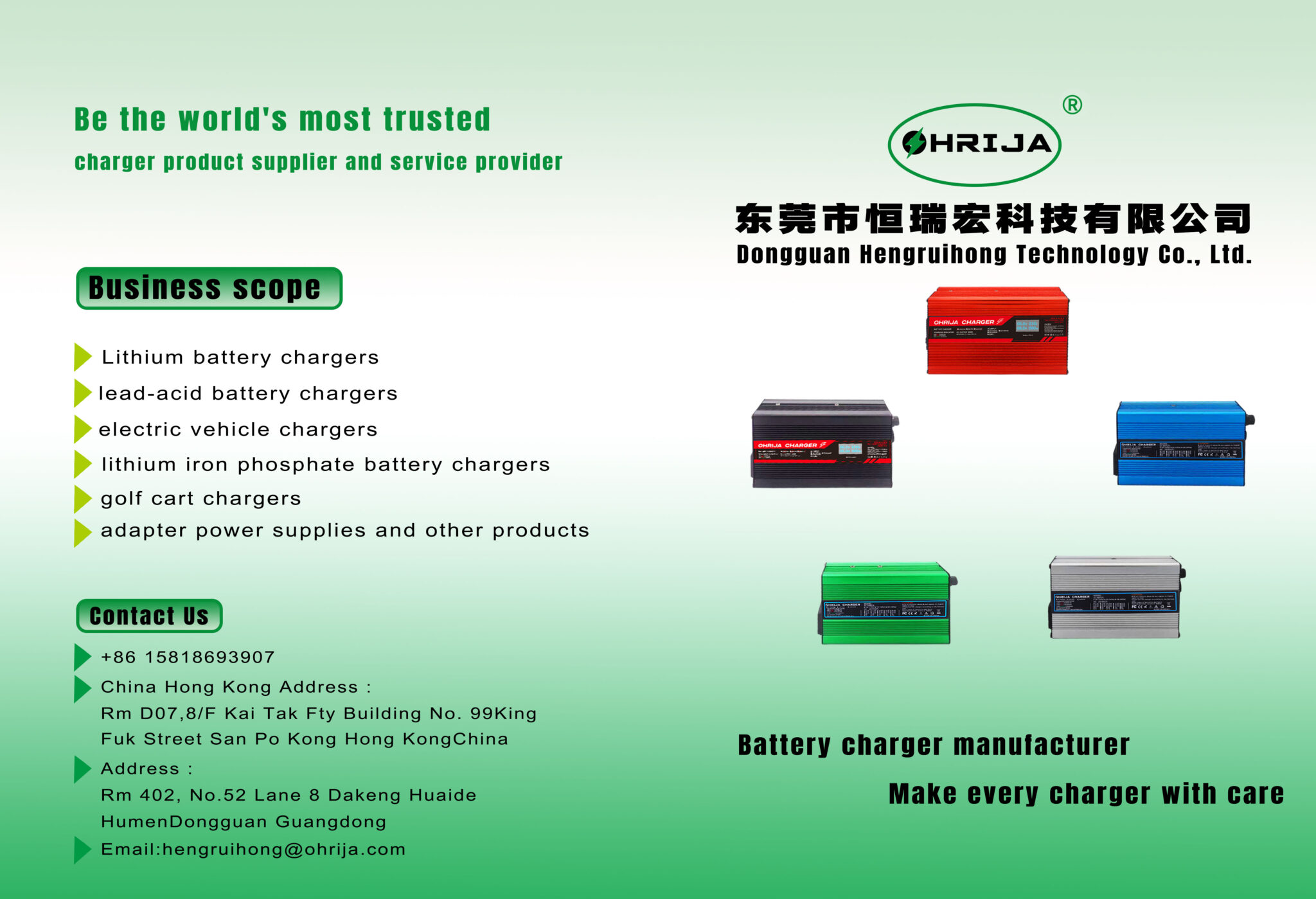
OHRIJA brand belongs to Dongguan Hengruihong Technology Co., Ltd., established in 2020 and headquartered in Dongguan, Guangdong Province, China. Our company is a high-tech enterprise integrating R&D, production, and sales. The company’s main products include lithium battery chargers, lithium iron phosphate battery chargers, lead-acid battery chargers, golf cart chargers, power adapters, and custom industrial switching power supplies.
Engineered with rugged extruded aluminum alloy enclosures, intelligent temperature-controlled cooling fans, multi-stage CC/CV microcontrollers, and comprehensive hardware protections (over-voltage, over-current, short-circuit, and reverse-polarity safeguards), OHRIJA chargers deliver dependable power conversion across demanding commercial and mobility environments.
Headquarters: Dongguan, Guangdong Province, China
Corporate Identity: Dongguan Hengruihong Technology Co., Ltd. (Est. 2020)
Core Technology: High-Frequency Switch-Mode Power Supply (SMPS) Platforms
Battery Chemistries: Lithium-Ion (NMC), LiFePO4, AGM, and Deep-Cycle Lead-Acid
Circuit Protections: OVP, OCP, SCP, Reverse Polarity, and Thermal Cutoff
Quality Testing: 100% Full-Load Burn-In, Automated Hi-Pot, and Drop-Tested Housings
View complete engineering data and browse our full catalog on the official OHRIJA battery CHARGER supplier portal.
Costly Mistakes Operators Make When Handling Battery Chargers
In our failure analysis audits of damaged charging units, hardware breakdowns almost always trace back to four common handling errors:
- Stacking Operational Chargers in Confined Cabinets: Placing active power supplies inside closed, unventilated toolboxes or stacking units directly on top of each other traps heat. As hot exhaust air recirculates into adjacent intake vents, internal temperatures quickly exceed 85°C, triggering continuous thermal throttling or blowing primary switching transistors. Always maintain at least six inches of clear, unobstructed airflow around all intake and exhaust surfaces.
- Cleaning Dust with Shop Air Laden with Moisture and Compressor Oil: Blowing out an electronic power supply with untreated shop air often sprays aerosolized moisture and lubricating oil across circuit traces. This oil-water mix traps future dust, creating conductive grime that ruins insulation resistance. Always use clean, dry instrument air or dedicated anti-static electronics dusters.
- Yanking on DC Leads to Disconnect Plugs: Pulling on the rubber cable jacket rather than gripping the plastic connector housing breaks the internal crimped wire connection. This causes high contact resistance, arcing, and intermittent connections. Always grip the molded plug housing directly when disconnecting.
- Ignoring Failed Internal Cooling Fans: When internal cooling fans begin squealing or stall completely, operators sometimes ignore the issue because the charger still powers on. Running high-current switching circuits without active airflow causes internal components to overheat within minutes, resulting in blown fuses and fried circuit boards. If a cooling fan fails to spin under load, take the charger out of service immediately and replace the fan.
Essential Sourcing and Hardware Selection Considerations
Before purchasing replacement chargers or outfitting a commercial facility, verify these four design and engineering specifications with your hardware supplier:
- Independent Thermal Protection and Sensor Redundancy: Ensure the charger incorporates multiple internal thermal sensors on primary heatsinks and secondary transformers. The control board must feature automatic thermal derating or shutdown if internal temperatures exceed safe operating limits.
- Conformal Coating on PCB Assemblies: For chargers operating in humid, coastal, or agricultural environments, confirm that internal circuit boards are treated with a thick, certified conformal coating (such as silicone or polyurethane resin). This protective layer shields fine solder joints and copper traces from humidity and corrosive vapors.
- Standardized, Readily Available Connector Architecture: Avoid non-standard, proprietary charging plugs that cannot be sourced through general electrical distributors. Insist on standardized, heavy-duty industrial connectors (such as Anderson SB50/SB175 or standard screw-lock aviation plugs) to ensure straightforward field maintenance and terminal replacement.
- Safety Certifications and Dielectric Isolation: Confirm that chargers carry legitimate international safety certifications (UL 1564, UL 1012, CE, or FCC Part 15 Class A/B) and undergo factory dielectric withstand testing (Hi-Pot) to guarantee safe electrical isolation between AC mains inputs and DC battery outputs.
Expert Recommendation and Electrical Management Verdict
In most professional situations, we recommend treating your battery charger as an essential companion to your energy storage system rather than a disposable accessory. A battery pack is only as reliable and safe as the power supply that charges it every day.
Allowing cooling fans to clog with dust, wrapping cables into tight knots, and ignoring output voltage drift are preventable mistakes that shorten hardware life and risk damaging expensive battery banks. By adopting a disciplined preventative routine—storing hardware in clean, climate-controlled spaces, clearing cooling passages bi-annually with dry compressed air, inspecting output terminals for arcing damage, and verifying CC/CV cutoff voltages with a true-RMS multimeter—you extend charger service life and protect connected battery assets. Partnering with a skilled, vertically integrated manufacturer like OHRIJA ensures your facility runs on rugged, thermally protected power supplies, delivering safe, efficient, and consistent charging cycles year after year.
Frequently Asked Questions (FAQ)
How often should battery chargers be inspected and cleaned?
In standard commercial and home workshop environments, chargers should receive a visual inspection and compressed air blowout every six months. In heavy industrial environments—such as dusty woodworking shops, metal fabrication facilities, or multi-shift fleet depots—air vents and cooling fans should be blown out monthly to prevent dust buildup and thermal throttling.
Why do battery charger DC connectors melt or overheat?
Connectors melt primarily due to high contact resistance caused by surface oxidation, dirt accumulation, worn spring tension, or contact pitting from disconnecting under load. High resistance generates concentrated heat under high currents (P = I^2 * R), softening plastic housings and damaging mating terminals.
Can storing a battery charger in a cold garage damage it?
Cold temperatures alone do not harm solid-state electronics, but rapid temperature swings create moisture condensation. Bringing a cold charger into a warm workspace causes condensation on internal circuit boards, creating short-circuit hazards and corroding copper traces when powered up. Always allow cold chargers to acclimate to room temperature in a dry environment before plugging them in.
Why should I turn off the AC power before unplugging the battery?
Disconnecting the DC plug while high current is flowing creates an inductive voltage spike as magnetic fields collapse inside the charger’s filter chokes. This spike jumps across the separating contact pins as an electric arc, burning away protective silver plating, causing contact pitting, and raising future electrical resistance.
What is electrolytic capacitor reforming, and why does it matter?
When a switch-mode charger sits unpowered for over a year, the aluminum oxide dielectric layer inside its electrolytic capacitors slowly breaks down. Reforming involves plugging the charger into AC power without a battery load for 30 to 45 minutes, allowing a gentle voltage to rebuild the insulating dielectric layer safely before placing the unit under full load.
Authoritative References
- IEEE Standards Association: IEEE 1188 Recommended Practice for Maintenance, Testing, and Replacement of Stationary Power Supplies
- Occupational Safety and Health Administration (OSHA): 29 CFR 1910.303 – General Electrical Safety Requirements and Equipment Maintenance
- National Fire Protection Association (NFPA): NFPA 70E Standard for Electrical Safety in the Workplace